Download
1 / 17
170 likes | 190 Views
This workshop discusses the ILC Beam Tests conducted in End Station A, including topics such as ESA equipment layout, wakefield studies, and bunch length diagnostics. It also covers the impact of the ILC parameters on detector design and the Machine-Detector Interface at the ILC.

E N D
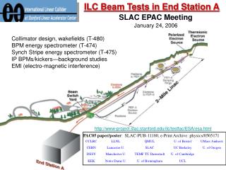
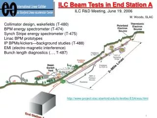
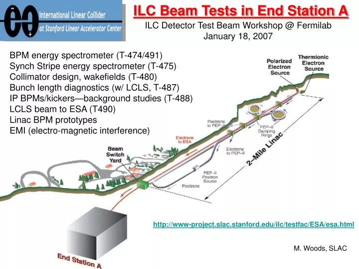
ILC Beam Tests in End Station A ILC Detector Test Beam Workshop @ Fermilab January 18, 2007 BPM energy spectrometer (T-474/491) Synch Stripe energy spectrometer (T-475) Collimator design, wakefields (T-480) Bunch length diagnostics (w/ LCLS, T-487) IP BPMs/kickers—background studies (T-488) LCLS beam to ESA (T490) Linac BPM prototypes EMI (electro-magnetic interference) http://www-project.slac.stanford.edu/ilc/testfac/ESA/esa.html M. Woods, SLAC
Talk by A. Sopczak Talk by M. Hildreth Talk by C. Clarke ESA Program and the ILC • Machine-Detector Interface at the ILC • Impact of ILC Parameters on Detector design and Physics reach • Impact of Detector designs on ILC design and parameters • (L,E,P) measurements: Luminosity, Energy, Polarization • Forward RegionDetectors • Collimation and Backgrounds • IR Magnets, Crossing Angle • EMI (electro-magnetic interference) in IR • MDI-related Experiments at SLAC’s End Station A • Collimator Wakefield Studies (T-480) • Energy spectrometer prototypes (T-474/491 and T-475) • IR background studies for IP BPMs (T-488) • EMI studies • Beam Instrumentation Experiments in ESA • Rf BPM prototypes for ILC Linac (part of T-474) • Bunch length diagnostics for ILC and LCLS (includes T-487)
ILC Beam Tests in End Station A • 6 test beam experiments approved: T-474, T-475, T-480, • T-487, T-488, T-490 • 2006 Runs: • January 5-9 commissioning run • April 24 – May 8, Run 1 • July 7-19, Run 2 • 2007 Runs (dates tentative): • March 7-26, Run 3 • July 5-8, T490 w/ LCLS beam • July 9-22, Run 4 • + requesting two 2-week runs in FY08
ILC Beam Tests in End Station A • 50 Participants at SLAC in 2006 for this program • 18 from SLAC + 32 users • 18 Institutions participated in 2006 beam tests and measurements • Birmingham U., Cambridge U., Daresbury, DESY, Dubna, Fermilab, KEK, • Lancaster U., Leland H.S., LLNL, Manchester U., Notre Dame U., Oxford U., • Royal Holloway U., SLAC, UC Berkeley, UC London, U. of Oregon Wakefield Studies from MCC T-474 and EMI Test Users in ESA Counting House
Beam Parameters at SLAC ESA and ILC *possible, using undamped beam
ESA Equipment Layout blue=FY06red=new in FY07 Wakefield box Wire Scanners FONT-T488 rf BPMs 18 feet Ceramic gap BLMs T-487: long. bunch profile Dipoles + Wiggler Upstream (not shown) Downstream (not shown) 4 rf BPMs for incoming trajectory Ceramic gap w/ rf diode detectors (16GHz, 23GHz, and 100GHz) and 2 EMI antennas Ceramic gap for EMI studies T475 Detector for Wiggler SR stripe
Installation of Beamline Components for 2006 Runs
EMI Studies in ESA US-Japan funds; Y. Sugimoto (KEK), G. Bower (SLAC), N. Sinev (U. of Oregon) • Characterized EMI along ESA beamline using antennas & fast 1.5GHz scope • Measured dependence of EMI antenna signals on bunch charge, bunch length 7.5GHz antenna near ceramic gap Also, WR10 and WR90 waveguides to Diode Detectors • waveform insensitive to beam conditions and bunch length (only see dependence on bunch length with 100GHz diode and pyroelectric detectors) • amplitude has linear dependence on bunch charge • data taken at different beamline locations; timing studies done to look for different sources • dominant source is exposed ceramic gap; smaller source from upstream toroid • → Reproduced and studied failure mode observed with SLD’s vertex detector • quantified failure rate at different EMI levels, varying geometry and shielding of electronics → Important to develop EMI standards in IR Region for Detector and Accelerator
Bunch Length Studies Collaborative effort with LCLS Collaborators: P. Emma, J. Frisch, R. Iverson, D. McCormick, S. Molloy, M. Ross,S. Walston, M. Woods • LCLS bunch length after BC-1 is 200mm rms, similar to 300mm ILC bunch length • commission + study high frequency diode and pyroelectric detectors to view radiation emitted at a ceramic gap -- detectors for future use at LCLS (ex. to use for phase feedbacks on Linac klystrons and sub-boosters) • provide necessary diagnostics to characterize ESA beam (ex. bunch length info is needed for T-480 collimator wakefield study) • Use A-line as a bunch compressor: • R56 = 0.465m (large) • 700mm rms bunch length at end of Linac with small chirp; • Sector-10 chicane off Radiated Power Spectrum at Ceramic Gap for sz=500um, 1/e decrease is at f=100GHz
Bunch Length Measurements vs Linac rf Phase Energy Spread 100GHz Diode* short bunches w/ small energy spread Shorter bunches LiTrack Simulation Data Pyroelectric Detector* → sensitive to shorter bunches than 100GHz diode! 23GHz Diode* → insensitive to bunch length *normalized to toroid
Tail sz= 0.734 mm Head A-Line Synchrotron Light Monitor signal w/ LOLA on. 1-m dispersion for horizontal axis. Calibrated vertical scale to be 0.32mm/deg; 1deg at S-band ~300um. Bunchlength + Energy-Z correlation Measurements at end of Linac with Transverse “LOLA” cavity 2006 Results (Preliminary) LiTrack Simulation: Linac RF phase = -10 deg, N = 1.6E10, VRTL = 38.5 MV Tail Head LiTrack Simulation sz= 0.523 0.009 mm measured bunchlength → first measurement of E-z correlation, using this technique! Technique will be used by LCLS.
Carousel of Gratings T487 (in FY07) Longitudinal Bunch Diagnostics for the ILC PI: G. Doucas (Oxford U.), Collaborating Institutions: U. of Oxford, Rutherford Appleton Lab, U. of Essex, Dartmouth College, SLAC • Goal: non-invasive determination of longitudinal bunch profile • Fundamental beam quantity; important for beam-beam effects. • Technique: Use Coherent Smith-Purcell radiation, • emitted when a beam passes close to a periodic structure (metallic grating) • Grating produces dispersion of the wavelengths according to the • angle of observation. • Wavelength distribution of emitted coherent radiation depends on • the temporal profile of the bunch • has previously been tested at lower energies w/ longer bunches and • lower bunch charges Winston Cone • Simple experimental set-up: • ‘Carousel’ of 3 gratings with different periodicities. • Array of 11 room temperature pyroelectric detectors • covering angular range 40 – 140o • w.r.t. the beam direction. Front View Waveguide Array Plate Filter
T-490 in FY07 LCLS Beam to ESA PI: M. Woods SLAC Collaborators: R. Arnold, P. Emma, T. Fieguth, C. Hast, M. Woods • Goals: • investigate capabilities for test beam experiments in ESA using the LCLS beam • commission accelerator safety systems for beam containment (BCS) and machine protection (MPS) when the LCLS injector is used. • characterize the transverse and longitudinal emittance of the beam in ESA. • Apparatus: • same as for the ILC-ESA tests (T-474 etc.) • install wire cards with 25-micron wires (rather than current 75-micron wires) • in the 2 ESA wire scanners for spotsize and emittance measurements. • use quad scans and wire scans for transverse emittance measurements. • use the transverse rf cavity LOLA, the A-Line synch lite monitor and • ESA bunch length diagnostics for longitudinal emittance measurements and • to measure E-z correlation Schedule: Tentative run dates are July 5-8, 2007 just prior to Run 4
SABER- assume SABER exists with bypass line and operational for beam tests by 2010 • - parameters for primary beam can be similar to ILC for bunch charge, energy spread, • bunch length. 28.5 GeV energy. • - limited space and infrastructure • - should be able to carry out small scale tests, ex. tests for BPMs, bunch length detectors • - unlikely to continue T-474/T-475 here; T-480 may be possible, but difficult • - need to investigate capability for low-intensity secondary beams for ILC detector R&D • ESA • several possibilities exist for primary and secondary beams to ESA in LCLS era; most • require PPS upgrade and some require pulsed magnets in Beam Switchyard • primary beam modes: i) high energy beam when LCLS not running, iii) extend SABER bypass line • to ESA (expensive), iii) interleaved 10Hz running using LCLS beam with pulsed magnets, • secondary beam modes: i) high energy beam when LCLS not running, ii) parasitic operation with LCLS • using beam halo and production collimator in BSY, iii) extend SABER bypass line to ESA (expensive), • iv) pulsed magnets in BSY using 10Hz LCLS beam and BSY production collimator, Future for continuing this ILC Test Beam Program? FY08→ continue program in ESA, requesting 4 weeks of Beam Tests → beam scheduling more difficult: priority for LCLS, also for SABER → reduced funding available (?) from SLAC and ILC, but major installations are complete FY09 and beyond (LCLS era, parasitic operation with PEP-II ends at end of FY08) → ESA PPS upgrade needed for continued ESA operation → ILC beam instrumentation tests in SABER are possible → Study group looking at SLAC test beam capabilities with primary and secondary beams for Detector and MDI-related R&D – need input from Fermilab ILC test beam workshop
Summary Very successful program in 2006! • 4 weeks of beam tests for 7 experimental programs • 50 participants from 18 institutions T-480 Collimator Wakefield Study • Results essential for ILC collimator design • Minimize risk for emittance degradation to IR and for achieving design luminosity T-474 and T-475 Energy Spectrometer Prototypes • Experimental results needed to demonstrate ability to meet design • goals for precise energy measurements for the ILC physics program. FY07→ strong program, with 5 weeks of Beam Tests planned FY08→ continue program, requesting 4 weeks of Beam Tests → beam scheduling more difficult: priority for LCLS commissioning, also for SABER → reduced funding available (?) from SLAC and ILC, but major installations are complete FY09 and beyond (LCLS era, parasitic operation with PEP-II ends at end of FY08) → ESA PPS upgrade needed for continued ESA operation → ILC beam instrumentation tests in SABER possible; secondary electron beam possible → Study group looking at SLAC test beam capabilities with primary and secondary beams for Detector and MDI-related R&D (need input from this workshop for user needs)
DRAFT of one summary table being prepared for a SLAC study on future of SLAC test beams beyond FY08 (also have other summary tables for individual BI, MDI, Detector tests)