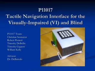
Self Navigation Device for the Blind
Our project aims to develop a portable navigation device designed specifically for visually impaired individuals. This innovative belt will utilize low-power vibrators to alert users of nearby objects, giving them crucial spatial awareness without the need for a traditional walking stick. By integrating sensors and an Arduino Due processor, real-time feedback is provided directly to the user’s torso, indicating obstacles on either side. Our goal is to empower the blind with greater independence while traveling in diverse environments, improving their overall quality of life.


Self Navigation Device for the Blind
E N D
Presentation Transcript
Self Navigation Device for the Blind ECE445 Senior Design Presentation Pradyut Paul and Christopher Cheung
Overview •We’d like to create a better, convenient way for visually impaired people to travel around •Our project will effectively guide the blind user without the need of a walking stick. –This belt will tell the user where objects are located. For example: if a person is walking and an object is detected to the left, using low powered vibrators, a small pulse will be sent to the left part of his/her torso indicating that the user cannot walk in that direction.
Overall Block Diagram Arduino Due Belt Sensors Headphones Vibrational Motors Audio Amplifier
Detection Algorithm Inputs Outputs Processor There are no objects around user Input from Sensor Data Detection Algorithm Object detected is steppable Object detected is NOT steppable
Components • Arduino Due Processor • Audio Amplifier Circuit • SD Card Shield • LV-MAXSONAR UltraSonic Sensor • Disc Coin Vibrational Motors • Power Circuit
Arduino Due Processor • Why? • In-built DAC • Requires 6 Analog inputs • Outputs 3.3V at digital pins • no need for 3V regulator • In-built PWM for pulse detection
Audio Circuit Function Amplifies the signal that comes from DAC1 pin on Arduino and outputs sound to user’s headphones
Audio Circuit Modifications Changes from Original Design: • Planned on using 5V from Arduino pin but volume was too soft • Changed our gain from 100 to 20 because the sound produced was loud enough for the user to hear • Ended up building circuit on perf board because PCB did not make it in time
SD Card Function Reads pre-recorded file on the SD card and sends signal to the arduino which converts it to an analog signal
SD Card Modifications • Decided to use the SD Card Reader instead of Arduino Ethernet Shield • less cost • less space
SD File Reading • Pre-recorded file requirement: • 16-bit resolution • Arduino DAC has resolution of 12, chops of last 4 bits • 44100Hz Sample Frequency • Stereo Output • Internal DAC has 2 channels which are always active
Output to DAC • Load into an array until the file is over • Arduino library “Audio” uses Audio.write to output array into DAC • Need to close file • If you do not -> plays only once
SD Card Issues Initial detection of a steppable object produced a clear and loud reading of the pre-recorded sound on the sd card but after first playback the sound produced had pauses during playback • Unable to resolve buffering problem even after reading through the arduino’s audio prepare and read header files • Issue remained after removing unnecessary testing code
Step Detection • Two Parts: • Reading data from sensors • Filtering • Analyze data for height detection
Chaining Sensors • Reading data from 1 sensor = OK • Reading data from multiple sensors simultaneously = BAD • Too much noise and cross-talk • Solution: Chain the sensors
Chaining Sensor Source: MaxBotix
Chaining Sensors • Reading occurs every 20ms for EACH sensor • Total delay time = 20ms x (# of Sensors) • Requires an initial ‘kickstart’ of 200ms • Signal sent from digital pin of Arduino
Reading Data • Sensor data comes into the analog port, which is converted to a decimal number from 0 to 1023 (10 bit resolution) • Reading occurs every 20ms per sensor, so we do not get a full reading until 100ms • Disadvantages: same topology cannot be used for faster moving devices like a car
Filtering Data • Sensors come with a in-built filter, but mainly filters any noise within the frequency range of the sensor • Our filter algorithm: • Collect 300 readings from each sensor • Bubble sort the data • Average only the middle 100 data points
Filtering Data • Advantages: • Filters out any outliers in the data array, while producing 1 value which is accurate to the degree of 2 units of the serial monitor (0->1023) • Disadvantages: • Requires too much time to filter, total time to analyze data is roughly 1.5 seconds
Filtering Data • After looking into delay problem, we found the source of the error to be the number of reads and the constant serial printing of data • After fixing problem, delay goes to ~.5 seconds
Step Detection • Original algorithm: • Take initial point and calibrate it to the users height. Initial reading: X • Once an object is read, second reading: Y • Pre-determined angle: 30 degrees • Object height =
Step Detection • Problems: • Requires that no objects are present in the vicinity: very unideal • Initial setup calibration time of 1 second: must remain very steady as soon as belt is put on: unideal
Step Detection • Second approach: • Manually calibrate it for a certain height • How can we incorporate it into other users? • Manually calibrate it for multiple heights by the increment of 1 inch • Build a UI that incorporates the user to input the height of the belt
Step Detection • Problems: • Much more work for the user • Requires the user to know the height of the torso or where the belt will be worn
Disk Coin Vibrational Motors • Small Samsung Disk Coin motors • Ideal for project since they use very less current and require only 1.3V to run • Instead of increasing the voltage to the motors, we varied the intensity via the PWM
Disk Coin Vibrational Motors • Intensity Algorithm There are no objects around user Motors do not turn on PWM output of 255 if object is within 1 step There are objects around user Motors turn on PWM output of 100 if object is between 2 steps and 1 step
Power Circuit • Each sensor requires 3.3V and 2mA to run • Along with that each BW pin needs to be pulled ‘high’ • Running each sensor from Arduino output of 3.3V = BAD • Not enough current drawn to each sensor • Not enough to pull up BW pins
Power Circuit • Solution = Voltage regulation of 9V battery!
Requirements for the Power Circuit • Voltage to each sensor must not exceed 3.3V and must not be less than 3.1V, plus or minus .1V • Verified by measuring voltages to each sensor via oscilloscope: average voltage 3.24V
Further Advances in Our Project • Build the belt to be more sturdy without hanging wires • Incorporate a UI that will let the user input their respective height • Fixing the audio player so it is clear every time • Add more sensors and vibrators for a higher resolution reading • Optimize algorithm to minimize delay
THANK YOU! • We appreciate your time and would like to open up to any questions and/or comments