Torsion in Girders
110 likes | 479 Views
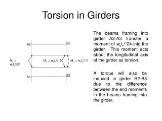
Torsion in Girders. The beams framing into girder A2-A3 transfer a moment of w u l n 2 /24 into the girder. This moment acts about the longitudinal axis of the girder as torsion. B2. A2. M u = w u l n 2 /24. M u = w u l n 2 /10. M u = w u l n 2 /11.

Torsion in Girders
E N D
Presentation Transcript
Torsion in Girders The beams framing into girder A2-A3 transfer a moment of wuln2/24 into the girder. This moment acts about the longitudinal axis of the girder as torsion. B2 A2 Mu = wuln2/24 Mu = wuln2/10 Mu = wuln2/11 A torque will also be induced in girder B2-B3 due to the difference between the end moments in the beams framing into the girder. B3 A3
Girder A2-A3 A2 A3 A2 A3 Torsion Diagram
Strength of Concrete in Torsion where, Acp = smaller of bwh + k1h2f or bwh + k2hf(h - hf) Pcp = smaller of 2h + 2(bw+ k1hf) or 2(h + bw) + 2k2(h - hf) As for shear, ACI 318 allows flexural members be designed for the torque at a distance ‘d’ from the face of a deeper support.
Redistribution of Torque p. 44 notes-underlined paragraph When redistribution of forces and moments can occur in a statically indeterminate structure, the maximum torque for which a member must be designed is 4 times the Tu for which the torque could have been ignored. When redistribution cannot occur, the full factored torque must be used for design. In other words, the design Tmax = 4Tc if other members are available for redistribution of forces.
Torsion Reinforcement • Stresses induced by torque are resisted with closed stirrups and longitudinal reinforcement along the sides of the beam web. • The distribution of torque along a beam is usually the same as the shear distribution resulting in more closely spaced stirrups.
Design of Stirrup Reinforcement Aoh= area enclosed by the centerline of the closed transverse torsional reinforcement At = cross sectional area of one leg of the closed ties used as torsional reinforcement st = spacing required for torsional reinforcment only sv = spacing required for shear reinforcement only S = stirrup spacing
Design of Longitudinal Reinforcement Al = total cross sectional area of the additional longitudinal reinforcement required to resist torsion Ph = perimeter of Aoh max. bar spacing = 12” minimum bar diameter = st/24
Cross Section Check To prevent compression failure due to combined shear and torsion:
Design of Torsion Reinforcementfor Previous Example p. 21 notes Design the torsion reinforcement for girder A2-A3. 30 ft 30 ft 30 ft 30 ft 24 ft 24 ft 24 ft