Serial Communication TX RX 8bits Interrupt on Receiver Full
180 likes | 209 Views
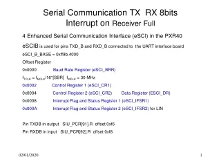
Serial Communication TX RX 8bits Interrupt on Receiver Full. 4 Enhanced Serial Communication Interface (eSCI) in the PXR40 eSCIB is used for pins TXD_B and RXD_B connected to the UART interface board eSCI_B_BASE = 0xff9b.4000 Offset Register

Serial Communication TX RX 8bits Interrupt on Receiver Full
E N D
Presentation Transcript
Serial Communication TX RX 8bitsInterrupt on Receiver Full 4 Enhanced Serial Communication Interface (eSCI) in the PXR40 eSCIB is used for pins TXD_B and RXD_B connected to the UART interface board eSCI_B_BASE = 0xff9b.4000 Offset Register 0x0000 Baud Rate Register (eSCI_BRR) fTCLK = fMCLK/16*[SBR] fMCLK = 30 MHz 0x0002 Control Register 1 (eSCI_CR1) 0x0004 Control Register 2 (eSCI_CR2) Data Register (ESCI_DR) 0x0008 Interrupt Flag and Status Register 1 (eSCI_IFSR1) 0x000A Interrupt Flag and Status Register 2 (eSCI_IFSR2) for LIN Pin TXDB in output SIU_PCR[91].R offset 0xf6 Pin RXDB in input SIU_PCR[92].R offset 0xf8
eSCI_BRR et eSCI_CR1 Baud Rate Register (eSCI_BRR) fTCL K = 9600bauds eSCI_BRR.R = 195 Control Register 1 (eSCI_CR1) eSCI_B.CR1.RIE = 1 Receiver Full Interrupt Enable. eSCI_B.CR1.TE = 1 Transmitter enable eSCI_B.CR1.RE = 1 Receiver enable eSCI_B.CR1.PE = 0 Parity bit generation and checking disabled. eSCI_B.CR1.ILT = 0 Idle line detection starts after reception of a low bit. eSCI_B.CR1.R = 0x002C
eSCI_CR3 et eSCI_DR Control Register 3 (eSCI_CR3) M2 This control bit together with the M bit of the Control Register 1 (eSCI_CR1) controls the frame format used This register is used to control the frame formats and the generation of the ERR bit in the SCI Data Register SCI Data Register (ESCI_DR) RD[7:0] write data 8 bits with M2 = 0 et M = 0
INTC Block Diagram Priority Select Register PSR Current Priority Register: CPR (between all peripheral interrrupts)
Hardware vector mode A l’adresse IVPR + n*0x0010 un espace mémoire est réservé n est le numéro du périphérique générant l’interruption acceptée 16 octets pour mettre le code permettant le saut absolu au programme d’interruption
INTC Priority Select Registers (INTC_PSRn) The individual interrupt priorities are selected in INTC_PSRn, where the priority select register is assigned accordingto the vector number.
INTC_CPR INTC Current Priority Register (INTC_CPR)
INTC_EOIR INTC End-of-Interrupt Register (INTC_EOIR) INTC End-of-Interrupt Register (INTC_EOIR) For possible future compatibility, write four bytes of all 0’s to the INTC_EOIR.
INTC_MCR • union { /* Module Configuration Register */ • vuint32_t R; • struct { • vuint32_t:26; • vuint32_t VTES:1; • vuint32_t:4; • vuint32_t HVEN:1; • } B; • } MCR;
INTC_CPR • union { /* Current Priority Register */ • vuint32_t R; • struct { • vuint32_t:28; • vuint32_t PRI:4; • } B; • } CPR;
INTC_EOIR union { /* End of Interrupt Register */ vuint32_t R; struct { vuint32_t EOIR:32; } B; } EOIR;
INTC_PSRn union { /* Priority Select Registers */ vuint8_t R; struct { vuint8_t:4; vuint8_t PRI:4; } B; } PSR[480];