Download
1 / 51
530 likes | 750 Views
ELE271 Topics covered on the final exam: 1. Number Representation : Binary, Data types, Computer arithmetic. 2. uP /MCU Architecture : Von Neumann, RISC/CISC. 3. Machine Code : Assembly, Disassembly, length, cycle 4. Assembly Code : instructions, lables , branching

E N D
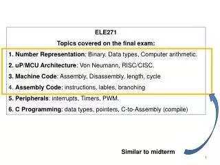
ELE271 Topics covered on the final exam: 1. Number Representation: Binary, Data types, Computer arithmetic. 2. uP/MCU Architecture: Von Neumann, RISC/CISC. 3. Machine Code: Assembly, Disassembly, length, cycle 4. Assembly Code: instructions, lables, branching 5. Peripherals: interrupts, Timers, PWM. 6. C Programming: data types, pointers, C-to-Assembly (compile) Similar to midterm
ELE271 Topics covered on the final exam: 1. Number Representation: Binary, Data types, Computer arithmetic. 2. uP/MCU Architecture: Von Neumann, RISC/CISC. 3. Machine Code: Assembly, Disassembly, length, cycle 4. Assembly Code: instructions, lables, branching 5. Peripherals: interrupts, Timers, PWM. 6. C Programming: data types, pointers, C-to-Assembly (compile) • Binary representation, Positional Notation. • Convert from binary to decimal and back. • 2’ Complement representation and operation • Subraction using 2’s complement addition. • Jimenez Ch.2
Positional Notation • In addition to the value depending on the symbol, the value also depends on its position relative to a decimal point • This allows us to represent any quantity by reusing the same set of symbols. • Countingrun through all available symbols then start again in the next position. • Example: What is the decimal value of 6,291? • 6,29110= 6103+ 2102+ 9101+ 1100 • 6thousands+2hundreds+ 9tens+ 1ones • For any radix, i i
most significant least significant 329 101 102 22 101 21 100 20 Unsigned Integers • Computers use weighted positional notation • What do these unsigned binary numbers represent? 3x100 + 2x10 + 9x1 = 329 1x4 + 0x2 + 1x1 = 5 0000 0110 1111 1010 0001 1000 0111 1100 1011 1001 0 15 1 7 11 6 10 8 12 9
Example • Convert the following binary numbers (expressions) to their decimal equivalent: 21 255 128 127 8 24
2’s Complement Integers To negate a number, 1’s complement + 1. Left-bit encodes sign: 0 = + (or 0) 1 = - • Representation • 00110binary 6decimal • 11010 -6 • 00000 0 • 11111 -1 • Range • –2(n-1)to 2(n-1)-1 • Simplifies logic circuit construction • Addition is performed using simple binary addition • Bottom line: simpler/faster hardware units.
2’s Complement Conversion • Positional number representation with a twist • the most significant (left-most) digit has a negative weight • Or count backwards ex. 1111 1101 • n-bits represent numbers in the range -2n-1 … 2n-1 - 1 • What are these 2’s complement numbers? 0110 = 22 + 21 = 6 1110 = -23 + 22 + 21 = -2 0000 0110 1111 1010 0001 1000 0111 1100 1011 1001 0 -8 6 7 -1 -4 -6 -5 1 -7
ELE271 Topics covered on the final exam: 1. Number Representation: Binary, Data types, Computer arithmetic. 2. uP/MCU Architecture: Von Neumann, RISC/CISC. 3. Machine Code: Assembly, Disassembly, length, cycle 4. Assembly Code: instructions, lables, branching 5. Peripherals: interrupts, Timers, PWM. 6. C Programming: data types, pointers, C-to-Assembly (compile) • uArchitecture vs. ISA • Von Neumann vs. Harvard • RISC vs. CISC • MSP430 Arch: 16-bit, registers. • Jimenez Ch.3
MSP430 Registers MSP430 Registers
Instruction Set Architecture (ISA) • The computer program (language) is translated into the instruction set of a particular computer • Specific to a CPU • Data types - what are the different representations of operands • Operations on data - what functions can be done • Addressable memory - where are operands stored • Addressing modes - how to find operands in memory
faster and more complex Microarchitecture • The microarchitecture transforms the ISA into an implementation. • 8051 • IA-32 • 386 • 486 • Pentium • Pentium-II, III, IV • Xeon • MSP430 • How the operations in the ISA are implemented • how do you add two binary numbers? • or, how do you access memory?
DATA MEMORY INSTRUCTION MEMORY Control & Address Data Instruction Control ALU CONTROL IN OUT CLOCK Status Von Neumann vs. Harvard Harvard Architecture • The Harvard architecture is a computer architecture with physically separate storage and signal pathways for instructions and data.
Address Bus Data Bus ALU Program Counter Instruction Register Von Neumann vs. Harvard The Von Neumann Computer MEMORY OUTPUT * monitor * printer * LEDs * D/A * disk INPUT * keyboard * mouse * scanner * A/D * serial * disk PROCESSING UNIT Von Neumannproposed this model in 1946 Registers Clock Control Logic The Von Neumann model:Program instructions and Data are both stored as sequencesof bits in computer memory Datapath Control
RISC vs. CISC RISC / CISC Architecture RISC CISC • Single-clock (Crit Path) • Reduced instructions • No microcode • Data explicitly accessed • Easier to validate • Larger code sizes (~30%) • Low cycles/second • More transistors on memory registers • Pipelining friendly • Emphasis on software (cheap) • Multi-clock • Complex instructions • Complicated microcode • Memory to memory operations • Difficult to validate • Smaller code sizes • High cycles/second • More transistors for complex instructions • Compiler friendly • Emphasis on hardware (expensive)
ELE271 Topics covered on the final exam: 1. Number Representation: Binary, Data types, Computer arithmetic. 2. uP/MCU Architecture: Von Neumann, RISC/CISC. 3. Machine Code: Assembly, Disassembly, length, cycle 4. Assembly Code: instructions, lables, branching 5. Peripherals: interrupts, Timers, PWM. 6. C Programming: data types, pointers, C-to-Assembly (compile) • Machine Code: Assembly & Disassembly
Machine vs Assembly Code Machine Code Assembly Code 0100000000110001 mov.w #0x0600,r1 0000011000000000 0100000010110010 mov.w #0x5a1e,&0x0120 Assembler 0101101000011110 0000000100100000 0100001100001110 mov.w #0,r14 0101001101011110 add.b #1,r14 1111000001111110 and.b #0x0f,r14 0000000000001111 Disassembler 0001001000110000 push #0x000e 0000000000001110 1000001110010001 sub.w #1,0(r1) 0000000000000000 0010001111111101 jne $-4 0100000100111111 mov.w @r1+,r15 Computer Instructions
Computer Instructions Anatomy of Machine Instruction “Add the value in Register 4 to the value in Register 5” add r4,r5 0101010000000101 How many source/destination registers can selected with a 4-bit field? 1. Verb –Opcode (0, 1, or 2 operands) 2. 1st object – Source Operand How many instructions are possible with a 4-bit op-code? 3. 2nd object – Destination Operand
Instruction Disassembly How to Disassemble MSP430 Code • Begin with a “PC” pointing to the first word in program memory. • Retrieve instruction word and increment PC by 2. • Find and list the corresponding instruction mnemonic using the opcode (most significant 4-9 bits). • Append “.b” or “.w” using the b/w bit (0=word, 1=byte). • If double operand instruction, decode and list source operand (Table 5). • If single or double operand instruction, decode and list destination operand (Tables 3 and 5). • If jump instruction, sign extend the 10-bit PC offset, multiply by 2, and add to the current PC. List that address.
Instruction Disassembly Addressing Modes Source Destination
ELE271 Topics covered on the final exam: 1. Number Representation: Binary, Data types, Computer arithmetic. 2. uP/MCU Architecture: Von Neumann, RISC/CISC. 3. Machine Code: Assembly, Disassembly, length, cycle 4. Assembly Code: instructions, lables, branching 5. Peripherals: interrupts, Timers, PWM. 6. C Programming: data types, pointers, C-to-Assembly (compile) • Addressing Modes • Jump calculation • Instruction Types (double-operand, etc). • Jimenez Ch.4
Computer Instructions Instruction Addressing Modes • Machine language instructions operate (verb) on operands (objects). • Addressing modes define how the computer identifies the operand (or operands) of each instruction. • Operands are found in • registers, • instructions, or • memory. • Memory operands are accessed • directly, • indirectly (pointer), or • indexed.
MSP430 ISA RISC/CISC machine 27 orthogonal instructions 8 jump instructions 7 single operand instructions 12 double operand instructions 4 basic addressing modes. 8/16-bit instruction addressing formats. Memory architecture 16 16-bit registers 16-bit Arithmetic Logic Unit (ALU). 16-bit address bus 16-bit data bus (8-bit addressability) 8/16-bit peripherals MSP430 ISA
Computer Instructions Computer Instructions • Computer program consists of a sequence of instructions • instruction = verb + operand(s) • stored in memory as 1’s and 0’s • called machine code. • Instructions are fetched from memory • The program counter (PC) holds the memory address of the next instruction (or operand). • The instruction is stored internal to the CPU in the instruction register (IR). • Programs execute sequentially through memory • Execution order is altered by changing the Program Counter. • A computer clock controls the speed and phases of instruction execution.
MPS430 Instruction Formats Format I: Instructions with two operands: MSP430 Instructions • Format II: Instruction with one operand: • Format III: Jump instructions:
Example: Double Operand Copy the contents of a register to another register Assembly: mov.w r5,r4 Instruction code: 0x4504 One word instruction The instruction instructs the CPU to copy the number in register r5 to register r4 Double Operand Instructions
Jump Instruction Format Jump instructions are used to direct program flow to another part of the program. The condition on which a jump occurs depends on the Condition field consisting of 3 bits: 000: jump if not equal (Z 1) 001: jump if equal (Z=1) 010: jump if carry flag equal to zero (C 1) 011: jump if carry flag equal to one (C=1) 100: jump if negative (N = 1) 101: jump if greater than or equal (N = V) 110: jump if less than (N V) 111: unconditional jump Jump Instructions
Jump Instruction Format Jump instructions are executed based on the current PC and the status register Conditional jumps are controlled by the status bits Status bits are not changed by a jump instruction The jump off-set is represented by the 10-bit, 2’s complement value: Thus, the range of the jump is -511 to +512 words, (-1023 to 1024 bytes ) from the current instruction Note: Use a BR instruction to jump to any address Jump Instructions
Example: Jump Format Continue execution at the label main if the carry bit is set Assembly: jc main Instruction code: 0x2fe4 One word instruction The CPU will add to the incremented PC (R0) the value -28 x 2 if the carry is set Jump Instructions
Instruction Disassembly Addressing Modes Source Destination
MSP430 Clock Cycles Instruction Clock Cycles • Generally, 1 cycle per memory access: • 1 cycle to fetch instruction word • +1 cycle if source is @Rn, @Rn+, or #Imm • +2 cycles if source uses indexed mode • 1st to fetch base address • 2nd to fetch source • Includes absolute and symbolic modes • +2 cycles if destination uses indexed mode • +1 cycle if writing destination back to memory • +1 cycle if writing to PC (R0) • Jump instructions are always 2 cycles
ELE271 Topics covered on the final exam: 1. Number Representation: Binary, Data types, Computer arithmetic. 2. uP/MCU Architecture: Von Neumann, RISC/CISC. 3. Machine Code: Assembly, Disassembly, length, cycle 4. Assembly Code: instructions, lables, branching 5. Peripherals: interrupts, Timers, PWM. 6. C Programming: data types, pointers, C-to-Assembly (compile) • Processing an interrupt • Interrupt-Driven Programming • Timers • PWM • Jimenez 4.8,6.3.0-6.3.3, 6.4 7.2, 7.3.0, 7.3.1, 7.3.2, 7.4.
Interrupts Processing an Interrupt… • Processor completes execution of current instruction. • Master Clock (MCLK) started (if CPU was off). • Processor pushes Program Counter (PC) on stack. • Processor pushes Status Register (SR) on stack. • Interrupt w/highest priority is selected. • Interrupt request flag cleared (if single sourced). • Status Register is cleared: • Disables further maskable interrupts (GIE cleared) • Terminates low-power mode • Processor fetches interrupt vector and stores it in the program counter. • User ISR must do the rest!
What happens during an interrupt. 1. An interrupt has to be requested by the peripheral (IRQ). 2. The peripheral interrupt enable (PIE) bit must be set. 3. The General Interrupt Enable (GEI) bit must be set. 4. An Interrupt Service Routine (ISR) has to be run. First.asm
Interrupt Service Routine Interrupt Latency • The time between the interrupt request and the start of the ISR is called latency • MSP430 requires 6 clock cycles before the ISR begins executing • An ISR may be interrupted if interrupts are enabled in the ISR • Well-written ISRs: • Should be short and fast – get in and get out • Require a balance between doing very little – thereby leaving the background code with lots of processing – and doing a lot and leaving the background code with nothing to do • Applications that use interrupts should: • Disable interrupts as little as possible • Respond to interrupts as quickly as possible
Multi-Source Interrupt Handlers Solution: poll the interrupt flags to determine which port issued the interrupt. For example: port2_ISR: bit.b #BIT6,&P2IFG ; S1 Interrupt? jz end ; if not, exit
Frequency Duty Cycle Pulse Width Modulation 0xFFFF TACCR0 TACCR1 0x0000 P1.0 TAIFG1 TAIFG0
Frequency Duty Cycle Timer PWM ISR
ELE271 Topics covered on the final exam: 1. Number Representation: Binary, Data types, Computer arithmetic. 2. uP/MCU Architecture: Von Neumann, RISC/CISC. 3. Machine Code: Assembly, Disassembly, length, cycle 4. Assembly Code: instructions, lables, branching 5. Peripherals: interrupts, Timers, PWM. 6. C Programming: data types, pointers, C-to-Assembly (compile) • C Data Types: int, pointers • C Compiling (C-to-Assembly) • Jimenez Ch.5
Conditinal Jump and Control Structures Start with an algorithm in pseudocode/Java/C: unsigned integer If ( a >= b ) { a = a + b } else { a = a -b } 1. Resource allocation Assign variables to registers 2. Convert to Register Transfer Notation Swap out variables with registers Change “=“ to “<-” a => r5 b => r6 if( r5 >= r6 ){ r5 <- r5 + r6 } else { r5 <- r5 – r6 } 3. RTN to Assembly Match forms of Algothm->Assembly Insert Opcodes. cmp r5,r6 jhsNotLessThan sub r5,r6 jmp End NotLessThan: add r5,r6 End:
RTN to Assembly: The While Statement Part 2 Usually a “while” statement implies a “cmp” “while” loops cause jmp backwards while ( n > 0 ) { s1… } Loop: cmp #0,r6 dec r6 jz End s1… jmp Loop End: Until condiion is met, then Jmp forward.
h e l l o \0 a: w o r l d \0 p: Arrays and Pointers • Array names are NOT pointer variables • char a[6]; • Requests memory for 6 characters, to be known by the name “a”. • “a” is not a variable and known only at compile time (ie. defined in the compiler symbol table). • char *p; • Requests memory for a single pointer variable, to be known by the name “p”. • “p” can point to any char (or contiguous array of chars). • Example: char a[] = "hello"; char *p = "world";
* =dereference & = reference Pointers Operator Precedence and Associativity
2 5 2 3 6 // y = a[0]+1 y=2, ip=0x05f2 // a[0] = a[0]+1 y=2, ip=0x05f2 0x05f4 // y = ++a[0] y=3, ip=0x05f2 // y = a[0], ip++ y=3, ip=0x05f4 // y=a[1], a[1]++ y=5, ip=0x05f4 Pointer Arithmetic Incrementing Pointers • A pointer increments according to its type. • The unary operators * and & bind more tightly than arithmetic operators. 0 3 int y = 0; int a[5] = {1, 5, 9, 13, 17}; int* ip = &a[0]; y = *ip + 1; *ip += 1; y = ++*ip; y = *ip++; y = (*ip)++; 1 5 9 13 17 0x05f2
Print to LCD using a pointer char string[]={‘H’,’i’,’8’,’6’,’\0’}; char *stringPtr= &string[0] halLcdPrintLine(stringPtr, 1, 0x04); Hi86