Download
1 / 15
150 likes | 281 Views
This document details the setup and preliminary findings from the Time-of-Flight (TOF) system in the ongoing TPC experiment conducted by Mizuki Sumihama on May 2, 2008. The study focuses on resolving 2 ns timing ambiguities using tagger plastic counters in tandem with the New-DC components. We aim to accurately measure missing mass spectra for K+ and proton events, evaluating the capability of the new TPC for tracking momentum vectors and vertex points amidst mixed magnetic fields. The findings signify challenges and proposed improvements in the setup and data interpretation.

E N D
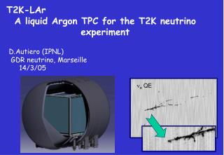
TOFfor New-TPC experiment Mizuki Sumihama May, 2nd, 2008 Time-of-Flight Missing mass of single-K+, proton New-DC
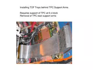
Setup of forward TPC New-DC DC1 DC2 DC3 TOF Dipole ~ 1 m FWD(Plastic) -1745 -830 -460 +1000 +3100 [mm] Momentum: No SVTX(SSD) , New-DC TOF : rf-TOF-wall , (Distance between target and fwd is ~1m.)
Tagger-Plastic counters for 2 nsec structure of RF signals Standard setup : We use Start counter to solve 2 ns ambiguity of RF signals. But New-TPC exp. : Distance between TGT and FWD is about 1m (too long!), and TOF between TGT and FWD is not negligible and difficult to solve the 2 ns ambiguity. Use tagger plastic counters
2 nsec structure in Tagger Before time-work correction After time-work correction 2 ns ambiguity can be solved by Tagger plastic counters
Mass spectra Few events not to solve 2ns-ambiguity.
Missing mass spectra ~5 days Eg < 2 GeV Eg < 2.4 GeV All n(p+) MM(K+) MM(p) Eg function up to 3GeV temporary determined by Kato w p0, h Require a hit in outers No signal of p0, h
Plots from the data with standard setup –Not any request at side region q<25 degree np0 h MM(K+) MM(p)
Z-vertex Target position q < 14 degree Polar angle for single track Vertex resolution for 2 track events is not good because of No SVTX(SSD) and small opening angles. improvement including New-DC ??
TOF with Tag-PL and Outers Front view of TDC, Inner and Outer • One-side readout for Inner • counters, time resolution is • about 800 ps by Yamamura. • Start timing is determined • by RF signals and solve 2 ns • ambiguity by Tagger-PL. • Stop timing is determined by • Outers. Time resolution is • about 200 ps by Yamamura.
b vs. momentum,dE/dx Information of path length, momentum and dEdx by Nakatsugawa-kun.
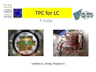
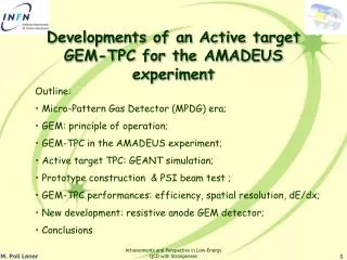
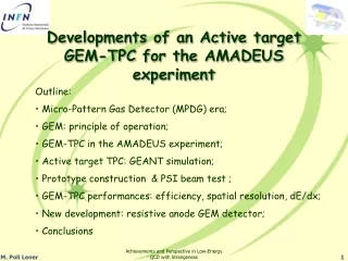
New-DC • Accept events go through forward. • Help to determine momentum vector • and vertex points in mixed magnetic field • of Dipole and Solenoid . TPC • Pitch 14 mm • YY’UU’VV’ 6 planes • U/V angle 30 degree • the same as DC2 and DC3 Forward LEPS New-DC Installation of NDC in program for side tracking (TPCana) is by Uchida.
Magnetic field New-DC ~0.1T ~0.05T
Cathode sheet (aluminized mylar) 12.5μm New DC DC0 V V’ U U’ Y 7mm Y’ 7mm 7mm 97mm sense wire (Au-W) φ30μm #50×6 Layer potential wire (Au-BeCu) φ100μm #50×6 Layer
xt-curve Expected hit position - Wire position Trace back from DC1 to each planes of NDC and determine initial xt-curve. iteration to have better xt curve. Solve left-right ambiguity By positions of fired wires In Y/Y’, U/U’ and V/V’. Require 6 hits in NDC. Y Y’ U U’ V V’
outlook Egamma calibration up to 3 GeV Alignment of New-DC Require hits in all 6 planes relax to 5 or 4 hits. The number of clusters in NDC is sometime huge. need a cut condition by an efficient /safety way Check run dependence of t0/xt-curve ………………..