Introduction to Fault-Tolerant Systems: Checkpointing and Recovery Protocols
370 likes | 466 Views
Learn about checkpointing, rollback recovery schemes, system models, interactions with the outside world, garbage collection, checkpoint-based protocols, and more in fault-tolerant systems.

Introduction to Fault-Tolerant Systems: Checkpointing and Recovery Protocols
E N D
Presentation Transcript
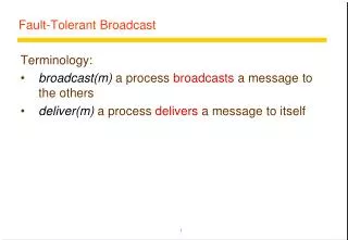
Fault Tolerant Systems Checkpointing and Rollback Recovery Protocols
Introduction • Rollback recovery treats a distributed system as a collection of processes that communicate through a network • Fault tolerance is achieved by periodically using stable storage to save the processes’ states during the failure-free execution. • Upon a failure, a failed process restarts from one of its saved states, thereby reducing the amount of lost computation. • Each of the saved states is called a checkpoint
Different Rollback Recovery Schemes Rollback Recovery Schemes Checkpoint based Log based Uncoordinated check pointing Pessimistic Logging Coordinated check pointing Optimistic Logging Comm. induced check pointing Casual Logging
Checkpoint based Recovery: Overview • Uncoordinated checkpointing: Each process takes its checkpoints independently • Coordinated checkpointing: Process coordinate their checkpoints in order to save a system-wide consistent state. This consistent set of checkpoints can be used to bound the rollback • Communication-induced checkpointing: It forces each process to take checkpoints based on information piggybacked on the application messages it receives from other processes.
System Model • System consists of a fixed number (N) of processes which communicate only through messages. • Processes cooperate to execute a distributed application program and interact with outside world by receiving and sending input and output messages, respectively. Output Messages Input Messages Outside World Message-passing system P0 m1 P1 m2 P2
Consistent System State • A consistent system state is one in which if a process’s state reflects a message receipt, then the state of the corresponding sender reflects sending that message. • A fundamental goal of any rollback-recovery protocol is to bring the system into a consistent state when inconsistencies occur because of a failure.
Example Consistent state P0 m1 P1 m2 P2 Inconsistent state P0 m1 P1 m2 P2 “m2” becomes the orphan message
Checkpointing protocols • Each process periodically saves its state on stable storage. • The saved state contains sufficient information to restart process execution. • A consistent global checkpoint is a set of N local checkpoints, one from each process, forming a consistent system state. • Any consistent global checkpoint can be used to restart process execution upon a failure. • The most recent consistent global checkpoint is termed as the recovery line. • In the uncoordinated checkpointing paradigm, the search for a consistent state might lead to domino effect.
Domino effect: example Recovery Line P0 m7 m2 m5 m0 m3 P1 m6 m4 m1 P2 Domino Effect: Cascaded rollback which causes the system to roll back to too far in the computation (even to the beginning), in spite of all the checkpoints
Interactions with outside world • A message passing system often interacts with the outside world to receive input data or show the outcome of a computation. If a failure occurs the outside world cannot be relied on to rollback. • For example, a printer cannot rollback the effects of printing a character, and an automatic teller machine cannot recover the money that it dispensed to a customer. • It is therefore necessary that the outside world perceive a consistent behavior of the system despite failures.
Interactions with outside world (contd.) • Thus, before sending output to the outside world, the system must ensure that the state from which the output is sent will be recovered despite of any future failure • Similarly, input messages from the outside world may not be regenerated, thus the recovery protocols must arrange to save these input messages so that they can be retrieved when needed.
Garbage Collection • Checkpoints and event logs consume storage resources. • As the application progresses and more recovery information collected, a subset of the stored information may become useless for recovery. • Garbage collection is the deletion of such useless recovery information. • A common approach to garbage collection is to identify the recovery line and discard all information relating to events that occurred before that line.
Checkpoint-Based Protocols • Uncoordinated Check pointing • Allows each process maximum autonomy in deciding when to take checkpoints • Advantage: each process may take a checkpoint when it is most convenient • Disadvantages: • Domino effect • Possible useless checkpoints • Need to maintain multiple checkpoints • Garbage collection is needed • Not suitable for applications with outside world interaction (output commit)
Recovery Line Calculation • Recovery line can be calculated from the checkpoint schedule either using a rollback-dependency graph or a checkpoint graph. • Rollback Dependency Graph: • Construct the graph • Perform reachability analysis from the failure states • The recent states which are unreachable from the failed state form the recovery line.
Rollback Dependency Graph C00 C01 P0 P1 C10 C11 P2 P3 C00 C01 P0 Initially marked nodes P1 C11 C10 P2 Recovery Line P3
Recovery Line Calculation with checkpoint graph • Checkpoint graphs are very similar to the rollback-dependency graphs except that, when a message is sent from I(i,x), and received in I(j,y), a directed edge is drawn from C(i,x-1) to C(j,y) (instead of C(i,x) to C(j,y)) C01 C00 P0 P1 C10 C11 C00 C01 C00 P0 C01 P0 Rollback-dependency graph Checkpoint graph P1 P1 C10 C11 C10 C11
The Rollback Propagation Algorithm • Step 1: Include last checkpoint of each failed process as an element in set “RootSet”; • Step 2: Include current state of each surviving process as an element in “RootSet”; • While(at least one member of RootSet is marked) • Replace each marked element in RootSet by the last unmarked checkpoint of the same process; • Mark all checkpoints reachable by following at least one edge from any member of RootSet • End While • RootSet is the recovery line
Checkpoint Graph C00 C01 P0 P1 C10 C11 P2 P3 C00 C01 P0 P1 C11 C10 P2 Recovery Line P3
Garbage Collection • Any checkpoint that precedes the recovery lines for all possible combinations of process failures can be garbage-collected. • The garbage collection algorithm based on a rollback dependency graph works as follows: • Mark all volatile checkpoints and remove all edges ending in a marked checkpoint, producing a non-volatile rollback dependency graph. • Use reachability analysis to determine the worst-case recovery line for this graph, called the global recovery line.
Example Global Recovery Line Obsolete checkpoints C00 C01 P0 P1 C11 C10 P2 P3
Coordinated Checkpointing • Coordinated checkpointing requires processes to orchestrate their checkpoints in order to form a consistent global state. • It simplifies recovery and is not susceptible to the domino effect, since every process always restarts from its most recent checkpoint. • Only one checkpoint needs to be maintained and hence less storage overhead. • No need for garbage collection. • Disadvantage is that a large latency is involved in committing output, since a global checkpoint is needed before output can be committed to the outside world.
Different Coordinated Checkpointing Schemes Coordinated Checkpointing Schemes Blocking Non-blocking
Blocking Coordinated Checkpointing • Phase 1: A coordinator takes a checkpoint and broadcasts a request message to all processes, asking them to take a checkpoint. • When a process receives this message, it stops its execution and flushes all the communication channels, takes a tentative checkpoint, and sends an acknowledgement back to the coordinator. • Phase 2: After the coordinator receives all the acknowledgements from all processes, it broadcasts a commit message that completes the two-phase checkpointing protocol. • After receiving the commit message, all the processes remove their old permanent checkpoint and make the tentative checkpoint permanent. • Disadvantage: Large Overhead due to large block time
Non-blocking Checkpoint Coordination • The objective of the coordinated checkpointing is to prevent a process from receiving application messages that could make the checkpoint inconsistent. • General framework: • Checkpoint coordinator / initiator broadcasts the checkpointing message to every other node. • Each node upon receiving this message should take a checkpoint. • However, this approach could lead to checkpoint inconsistency
Non-blocking coordinated checkpointing Initiator Initiator P0 P0 m C0,x m C0,x P1 P1 C1,x Checkpoint Inconsistency C1,x With FIFO channels Initiator P0 m C0,x C1,x Non FIFO channels (small dashed line represents the piggybacked checkpoint request)
Synchronized Checkpoint Clocks • Loosely synchronized clocks can facilitate checkpoint coordination. • Loosely synchronized clocks can trigger the local checkpointing actions of all participating processes at approximately the same time without a checkpoint initiator. • A process takes a checkpoint and waits for a period that equals the sum of the maximum deviation between clocks and the maximum time to detect a failure in another process in the system. • The process can be assured that all checkpoints belonging to the same coordination session have been taken without the need of exchanging any messages.
Minimal checkpoint coordination • Coordinated checkpointing requires all processes to participate in every checkpoint. This approach is not scalable. • Basic Idea: Only those processes which communicated with the initiator directly or indirectly since the last checkpoint need to take new checkpoints.
Minimal checkpoint coordination (contd.) • Two Phase Protocol: • Phase 1: • Initiator sends a checkpoint request to all the processes which communicated with it since the last checkpoint. • Each process (Pi) which received this request forwards it to all the processes which communicated with (Pi) since the last checkpoint, and so on until no more processes can be identified. • Phase 2: • All processes identified in the first phase take a checkpoint
Communication-induced checkpointing • Avoids the domino effect while allowing processes to take some of their checkpoints independently. • However, process independence is constrained to guarantee the eventual progress of the recovery line, and therefore processes may be forced to take additional checkpoints. • The checkpoints that a process takes independently are local checkpoints while those that a process is forced to take are called forced checkpoints.
Communication-induced checkpoint (contd.) • Protocol related information is piggybacked to the application messages. • Receiver of each application message uses the piggybacked information to determine if it has to take a forced checkpoint to advance the global recovery line. • The forced checkpoint must be taken before the application may process the contents of the message, possibly incurring high latency and overhead. • Therefore, reducing the number of forced checkpoints is important. • No special coordination messages are exchanged.
Communication-induced Checkpointing schemes Communication induced Schemes Model-based checkpointing Index-based coordination
Model based checkpointing • Model-based checkpointing relies on preventing patterns of communications and checkpoints that could result in inconsistent states among the existing checkpoints. • A model is set up to detect the possibility that such patterns could be forming within the system, according to some heuristic. • A checkpoint is usually forced to prevent the undesirable patterns from occurring.
Index-based communication-induced checkpointing • Index-based checkpointing works by assigning monotonically increasing indexes to checkpoints, such that the checkpoints having the same index at different processes form a consistent state. • The indices are piggybacked on application messages to help receivers decide when they should force a checkpoint.
Log-based Recovery: Overview • It combines checkpointing with logging of nondeterministic events. • It relies on the piecewise deterministic (PWD) assumption, which postulates that all nondeterministic events that a process executes can be identified and that the information necessary to replay each event during recovery can be logged in the event’s determinant (all info. necessary to replay the event). • By logging and replaying the nondeterministic events in their exact original order, a process can deterministically recreate its pre-failure state even if this state has not been checkpointed. • Log-based rollback recovery is in general attractive for applications that frequently interact with the outside world which consists of input and output logged to stable storage.
Log-based recovery schemes • Schemes differ in the way the determinants are logged into the stable storage. • Pessimistic Logging: The application has to block waiting for the determinant of each nondeterministic event to be stored on stable storage before the effects of that event can be seen by other processes or the outside world. It simplifies recovery but hurts the failure-free performance. • Optimistic Logging: The application does not block, and the determinants are spooled to stable storage asynchronously. It reduces failure free overhead, but complicates recovery. • Casual Logging: Low failure free overhead and simpler recovery are combined by striking a balance between optimistic and pessimistic logging.