SIMBOL-X OPTICS
250 likes | 270 Views
This article investigates the design, calibration, and manufacture of the Simbol-X X-ray telescope optics, with a focus on the relation between weight and image quality. It also explores the feasibility of manufacturing the multilayer X-ray optics for Simbol-X.

SIMBOL-X OPTICS
E N D
Presentation Transcript
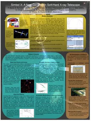
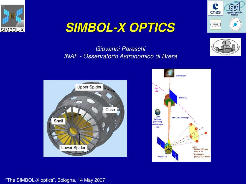
Upper Spider Case Shell Lower Spider SIMBOL-X OPTICS Giovanni Pareschi INAF - Osservatorio Astronomico di Brera
Basso et al., “The relation between the weight and the quality image in a X-ray telescope, with a particular regard to Simbol-X” Vernani, et al., “Feasibility study for the manufacturing of the multilayer x-ray optics for Simbol-X” Cotroneo et al, “Simbol-X mirror module design scientific optimization” Basso et al, “The problem of the calibration of SIMBOL-X X-ray telescope” Spiga et al., “ The scattering caused by microrougnhess in the Simbol-X multilayer coated optics” Romaine, et al, ”Multilayer coated hard X-ray mirrors based on Ni electroformed mirror shells” Poster presentation related to the SX optics implementation
Designing of the Simbol-X optics The technology for the optics fabrication Remarks on the calibration issue OUTLINE
rHEW = FL * HEW [rad] Advantages of focusing optics versus direct-view detectors HEW = Half Energy Width = circle where 50 % of focused photons is contained Moreover:much better imaging capabilities! B =background flux, Tint = integration time, DE = integration bandwidth
IMAGING (I) Osservazione XMM dello stesso campo tra 0.1 e 10 keV
1’ 10’ 10’ 10’ IMAGING (II) 50” HPD; eq. 2Crab 30”HPD Eq.2Crab 15”HPD Eq.0.2Crab
The focusing problem in the hard X-ray region (> 10 keV) Wolter I geometry Aeff F2 x qc2 x R2 but At photon energies > 10 keV the cut-off angles for total reflection are very small also for heavy metals the geometrical areas with usual focal lengths (> 10 m) are in general negligible F = focal length R = reflectivity L = mirror height q = incidence angle
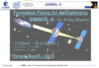
Multilayers Focal Length Vs. Diameters for SIMBOL-X and other X-ray telescopes 0.6 o The Formation Flight architecture offers the opportunity to implement long FL telescopes! Aeff F2 x qc2 x R2
Design Constraints • FOCAL LENGTH: ≥ 19 m (due to formation flight parameters) • DETECTOR SIZE: 7 +/1 cm (Size of the LED wafer + lateral ditering) • NUMBER OF MIRROR SHELLS: ≤ 100 • MAXIMUM DIAMETER: 70 cm (i.e. as XMM) • MINIMUM DIAMETER: ≥ 25 cm (to allow the multilayer deposition “post facto”) • MASS TO AREA RATIO: a reliable number in line with angular resolution of at least 20 arcsec HEW • MASS: not larger than 480 (TBD) including structure
Baseline SIMBOL-X Baseline Design detector size
Optics design • Heritage from XMM–Newton : nickel shells obtained by electroforming replication method; low mass obtained via a reduced thickness of shells • Coating : multi-layer Pt/C needed for requirement on large FOV and on sensitivity up to > 80 keV Focal length : 20 m Shell diameters : 30 to 70 cm Shell thickness : 0.2 to 0.6 mm Number of shells :100 N.B. I: The optics module will have both sides covered with thermal blankets N.B. II: a proton diverter will be implemented
ESA credits Mirror shell production by Ni electroforming replication BeppoSAX Jet-X/Swift XMM-Newton
Existing Coating Facilities at INAF-OAB & Media Lario Techn.
Thin JET-X shell : 25 arcsec Thickness Vs. Diameter trend for Ni-replicated optics HPD = 15 arcsec Year: 1994 HPD = 15 arcsec Year: 1999
A M/Acol computed rescaling to the correct focal length (20m) S B XMM f=7.5m JetX 1shell f=3.5m F M/Acol Dw R HEW 25” 12” Edge moment for a thin shell. Exponent ‘z’=1 Radial force for a thin shell. Exponent ‘z’=3 Wall thickness/diameter trade-off Mass including structure ≈480 kg Thicknesses ~ 2 times less than XMM
Section of the ring Upper Spider Case Shell Lower Spider The use of stiffening rings for handling and integration of thin mirror shells
Double grooves clips (DGC) Internal shaft (IS) IS DGC . . . . . Gluing of first set of DGC. Temporary IS can be used to apply control devises Removing of stiffening rings Positioning of second shell and gluing of second set of DGC Gluing of N shells on the upper spider and removing all DGC Removing temporary IS Repeated for N shell Integration procedure Temporary spider Temporary spider must give stiffness to the upper side of the entire set of shells and must be removed after gluing of all the shells on the upper spider.
C Pt Multilayer deposition system Deposition of the multilayer film onto the internal surface of a replicated mirror shell (development activity carried out so farin collaboration with the Harvard-Smithsonian CfA) particularly well suited for Simbol-X, since based on large diameter optics
Multilayer coated Ni mirror shells tested at Panter CREDITS: Panter/MPE
Simbol-X position * Fraction of the measured EA in double reflection for different lengths of the X-ray facility (as source-detector distance) for Simbol-X. The PANTER facility case corresponds approximately to the red line case. Possible Simbol-X position in the Panter facility for calibrations The long focal length calibration issue
Horizontal rotation correction • Comparators used to monitor the optic position during the optic spinning • Axial spin WM • Vertical tilt correction FM • Lateral correction Scheme of the manipulator: the possible movements/adjustments of the optical module are indicated Test of very long focal length optics (20 - 30 m) in pencil beam setup with more than 1 shell
By the end of the Phase a is planned to develope and calibrate a couple of multi-shell prototypes, caled down of a factor 2 wrt Simbol-X (Focal Length = 10 m, max diameter = 35 cm) It is planned the development of a diamond-turning facility for the madrel fabrication In Phase B a fully representative demonstrator will be developed and calibrated Programmatic points