Assembly Language Review
260 likes | 291 Views
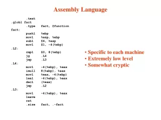
Assembly Language Review. Being able to repeat on the Blackfin the things we were able to do on the MIPS. Assembly code things to review 50% of ENCM369 in 50 minutes. YOU ALREADY KNOW HOW TO DO THESE THINGS ON THE MIPS Able to ADD and SUBTRACT the contents of two data registers

Assembly Language Review
E N D
Presentation Transcript
Assembly Language Review Being able to repeat on the Blackfin the things we were able to do on the MIPS Review of 50% OF ENCM369 in 50 minutes
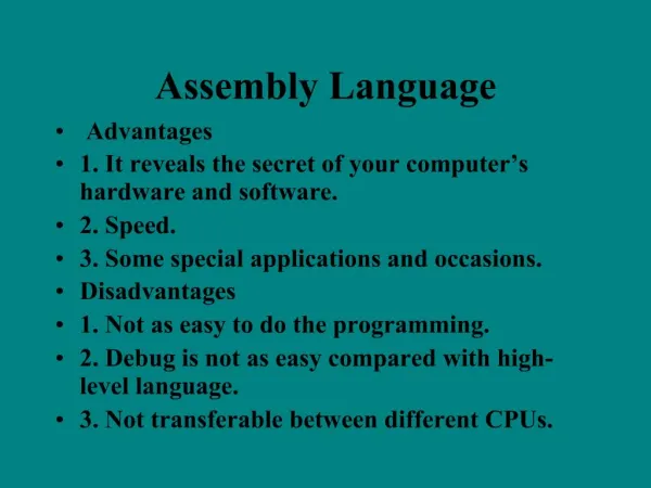
Assembly code things to review50% of ENCM369 in 50 minutes YOU ALREADY KNOW HOW TO DO THESE THINGS ON THE MIPS • Able to ADD and SUBTRACT the contents of two data registers • Able to perform bitwise AND operations, and perform bitwise OR operations the contents of two data registers • Able to place a (small) required value or bit pattern into a data register • Able to place a (large) required value or bit pattern into a data register • Being able to write a simple “void” function (function does stuff but does not return a result) • Being able to write a simple “int” function (function does stuff and returns a result in a specified register) • Being able to ADD and SUBTRACT the contents of two memory locations • IF YOU CAN DO THE SAME THING ON THE BLACKFIN – THEN THAT’S 50% OF THE LABS AND 50% OF EXAMS MATERIAL ACED
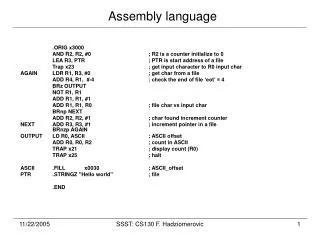
Able to ADD and SUBTRACT the contents of two data registers • It makes sense to ADD and SUBTRACT “values” stored in data registers • Blackfin DATA registers R0, R1, R2 and R3 • R0 = R1 + R2; // Additione.g. 4 + 6 10 (Decimal number) 0x14 + 0x16 0x2A (Hexadecimal number) • R3 = R1 – R2; // Subtraction e.g. 4 - 6 8 (Decimal number) 0x14 - 0x16 0xFFFFFFFE (Hexadecimal number) Review of 50% OF ENCM369 in 50 minutes
Able to perform bitwise AND and OR operations on data registers • It makes sense to perform OR and AND operations on “bit-patterns” stored in data registers. • NEVER perform ADD and SUBTRACT operations on “bit-patterns” stored in data registers. • WILL THIS BE EXAMINED? THIS CAUSES A CODE DEFECT • CODE DEFECT -- your test may (accidently) get the correct answer, but your production code fails at apparently random times. • Blackfin DATA registers R0, R1, R2 and R3 • R0 = R1 & R2; // Bitwise ANDe.g. B11001100 & B01010101 B01000100 • R3 = R1 | R2; // Bitwise ORe.g. B11001100 | B01010101 B11011101 Review of 50% OF ENCM369 in 50 minutes
Able to perform bitwise AND operations on data registers • KEY EMBEDDED SYSTEM OPERATION FOR CONTROLLING EMBEDDED DEVICES • For each corresponding bit in each register do • 0 & 0 = 0; 1 & 0 = 0; 0 & 1 = 0; 1 & 1 = 1 R1 = 0xCC = B 1100 1100 R2 = 0x55 = B 0101 0101 • R0 = R1 & R2; // Bitwise AND R1 = B 1 1 0 0 1 1 0 0 R2 = B 0 1 0 1 0 1 0 1 R0 = B 0 1 0 0 0 1 0 0 = 0x44 Review of 50% OF ENCM369 in 50 minutes
Able to perform bitwise OR operations on data registers • KEY EMBEDDED SYSTEM OPERATION FOR CONTROLLING EMBEDDED DEVICES • For each corresponding bit in each register do • 0 | 0 = 0; 1 | 0 = 1; 0 | 1 = 0; 1 | 1 = 1 R1 = 0xCC = B 1100 1100 R2 = 0x55 = B 0101 0101 • R0 = R1 | R2; // Bitwise OR R1 = B 1 1 0 0 1 1 0 0 R2 = B 0 1 0 1 0 1 0 1 R0 = B 1 1 0 1 1 1 0 1 = 0xDD Review of 50% OF ENCM369 in 50 minutes
Is it a bit pattern or a value?(Add, OR AND) Hints from “C++” If the code developer is consistent when writing the code then • Bit patterns are normally stored as “unsigned integers” e.g.unsigned int bitPattern = 0xFFA2345FF • Values are normally stored as “signed integers” e.g. signed int fooValue = -1; orint fooValue = -1; where the word “signed” is “understood”.Understood means “its there but not actually written down” (which means that it sometimes causes defects in your code – your code does not do what you expect) • Note that “bitPattern = 0xFFFFFFFF” and “fooValue = -1” are STORED as the SAME bit pattern 0xFFFFFFFFF in the registers and memory of MIPS and Blackfin processor Review of 50% OF ENCM369 in 50 minutes
Being able to place a required value into a data register –Part 1 • Like the MIPS, the Blackfin uses 32 bit instructions – all registers are the same size to ensure maximum speed of the processor (highly pipelined instructions). • The 32 bit Blackfin instruction for placing a value into a data register has two parts • to have16 bits available for describing the instruction • and 16 bits for describing the “signed” 16 bit value to be put into a R0 which is “signed” 32 bit data register. • The processor has to be told whether to put the 16 bits in the top part or the bottom part of the register Review of 50% OF ENCM369 in 50 minutes
Being able to place a required value into a data register –Part 1 • The 32 bit Blackfin instruction for placing a value into a data register has two parts • to have16 bits available for describing the instruction • and 16 bits for describing the “signed” 16 bit value to be put into a “signed” 32 bit data register. • This means that you have to use “2” 32-bit instructions to put large values into a data register (SAME AS MIPS). • Examples in next slides Review of 50% OF ENCM369 in 50 minutes
Placing a value into a data register Similar to MIPS, different syntax • R1 = 0; legal -- 0 = 0x0000 (signed 16 bits); (becomes the signed 32 bit 0x00000000 value after auto sign extension of the 16-bit value 0x0000) • R0 = 33; legal -- 33 = 0x0021 (signed 16 bits) (becomes the signed 32 bit 0x00000021 value after auto sign extension of the 16-bit value 0x0021) • R2 = -1; legal -- -1 = 0xFFFF (signed 16 bits) (becomes the signed 32 bit 0xFFFFFFFF value after auto sign extension of the 16-bit value 0xFFFF) • R3 = -33; legal -- -33 = 0xFFDE (signed16 bits) (becomes the signed 32 bit 0xFFFFFFDE value after auto sign extension of the 16-bit value 0xFFDE) Review of 50% OF ENCM369 in 50 minutes
Placing a “large” value into a data register • This approach does not work for any “large” value R1 = 40000; DOES NOT WORK WITH MIPS EITHERillegal -- as 40000 can’t be expressed as a signed 16-bit value – it is the positive 32 bit value 0x00009C40 If the assembler tried to take the bottom 16 bits of the decimal 40000 and sign extend it then this would happen “16-bit” hex value 9C40 (1001 1100 0100 0000) becomes “32-bit” hex value after sign extension 0xFFFF9C40 which is a “negative value” AND NOT WHAT YOU WANTED TO CODE • Therefore it is “illegal” to try to put a 32-bit value directly into a MIPS or a Blackfin processors (and many other processors). Review of 50% OF ENCM369 in 50 minutes
Placing a “large” value into a data register • If the assembler tried to take the bottom 16 bits of the decimal 40000 and sign extend it then this would happen “16-bit” hex value 9C40 (1001 1100 0100 0000) becomes “32-bit” hex value after sign extension 0xFFFF9C40 which is a “negative value” • “illegal” just as it would be in MIPS // Want to do R1 = 40000 // Instead must do operation in two steps as with MIPS #include <blackfin.h> R1.L = lo(40000); // Tell assembler to put “bottom” // 16-bits into “low” part of R1 register R1.H = hi(40000); // Tell assembler to put “top” // 16-bits into “high” part of R1 register
Placing a “large” value into a data register • A common error in the laboratory and exams is getting this two step thing “wrong” . Forgetting the second step is easy to do – just as easy to forget on Blackfin as on MIPS // Want to do R1 = 41235 – always need two MIPS or Blackfin instructions R1.L = lo(41235); // “bottom” 16-bits into “low” part of R1 register R1.H = hi(41325); // “top” 16-bits into “high” part of R1 registerTHIS SECOND STEP IS OFTEN A FORGOTTEN SECOND STEP RECOMMENDED SYNTAX TO AVOID “CODE DEFECTS”#define LARGEVALUE 41235 // C++ - like syntax R1.L = lo(LARGEVALUE); R1.H = hi(LARGEVALUE); Yes – you CAN put multiple Blackfin assembly language instructions on one line Review of 50% OF ENCM369 in 50 minutes
A “void” function returns NO VALUEextern “C” void Simple_VoidASM(void) #include <blackfin.h> .section program; .global _Simple_VoidASM; _Simple_VoidASM: _Simple_VoidASM.END: RTS; // Simple example Blackfin ASM function. Stays the same in final Things in red were cut-and-pasted using the editorto save Lab. time Review of 50% OF ENCM369 in 50 minutes
A simple “int” function return a valueextern “C” int Simple_IntASM(void) #include <blackfin.h> .section program; .global _Simple_IntASM; _Simple_IntASM: R0 = 7; // Return “7” _Simple_IntASM.END: RTS; Things in red were cut-and-pasted using the editor // Simple example Blackfin ASM function. Stays the same in final Review of 50% OF ENCM369 in 50 minutes
Being able to ADD and SUBTRACT the contents of two memory locations Let’s set up a practical situation • A “background” code thread is putting values into an array. Processor could be MIPS or Blackfin • For “background” thread read “interrupt service routine” or ISR. • ISR work “in parallel” with the “foreground” thread that is doing the major work on the microprocessor • Write a subroutine (returns int) that adds together the first two values of this shared array Review of 50% OF ENCM369 in 50 minutes
Start with a copy of the “int” function extern “C” int Simple_IntASM(void) #include <blackfin.h> .section program; .global _Simple_IntASM; _Simple_IntASM: R0 = 7; // Return “7” _SimpleInt_ASM.END: RTS; Things in red were cut-and-pasted using the editor Review of 50% OF ENCM369 in 50 minutes
Modify to be extern “C” int AddArrayValuesASM(void) #include <blackfin.h> .section program; .global _AddArrayValuesASM; _AddArrayValuesASM: R0 = 7; // Return “7” _AddArrayValuesASM.END: RTS; Things in red were cut-and-pasted using the editor Review of 50% OF ENCM369 in 50 minutes
Add a “data” array in assembly code #include <blackfin.h> .section L1_data; .byte4 _fooArray[42]; // Syntax for building an array // of 32-bit values .section program; .global _AddArrayValuesASM; _AddArrayValuesASM : R0 = 7; // Return “7” _AddArrayValuesASM .END: RTS; Things in red were cut-and-pasted using the editor Bonus marks in exams possible for ‘valid’ references to the ‘Hitch Hikers Guide’ and ‘Dr. Who’ Review of 50% OF ENCM369 in 50 minutes
Plan to return “sum”, initialize sum to 0 #include <blackfin.h> .section L1_data; .byte4 _fooArray[42]; .section program; .global _AddArrayValuesASM; _AddArrayValuesASM: #define sum_R0 R0 // register int sum; (Registerize int sum) sum_R0 = 0; // sum = 0; (Initialize sum) _AddArrayValuesASM .END: RTS; Things in red were cut-and-pasted using the editor Review of 50% OF ENCM369 in 50 minutes
Place the memory address of the start of the array into a pointer register …. Other code .section L1_data; .byte4 _fooArray[2]; .section program; .global _AddArrayValuesASM; _AddArrayValuesASM : #define sum_R0 R0 // register int sum; sum_R0 = 0; // sum = 0; #define pointer_to_array_P1 P1 // register int * pointer_to_array P1.L = lo(_fooArray); P1.H = hi(_fooArray); // pointer_to_array = &fooArray[0]; _AddArrayValuesASM .END: RTS; Things in red were cut-and-pasted using the editor P1 is a POINTER register(address register) Review of 50% OF ENCM369 in 50 minutes
Read the contents of the first array location into register R1 and add to sum_R0; …. Other code .section L1_data; .byte4 _fooArray[2]; .section program; .global _AddArrayValuesASM; _AddArrayValuesASM : #define sum_R0 R0 // register int sum; sum_R0 = 0; // sum = 0; #define pointer_to_array_P1 P1 // register int * pointer_to_array P1L = lo(_fooArray); P1.H = hi(_fooArray); // pointer_to_array = &fooArray[0];R1 = [pointer_to_array_P1]; // int temp = fooArray[0]; sum_R0 = sum_R0 + R1; // sum = sum + temp _AddArrayValuesASM.END: RTS; Things in red were cut-and-pasted using the editor Review of 50% OF ENCM369 in 50 minutes
Read the contents of the second array location into register R1 and add to sum_R0; …. Other code .section L1_data; .byte4 _fooArray[2]; .section program; .global _AddArrayValuesASM; _AddArrayValuesASM: #define sum_R0 R0 // register int sum; sum_R0 = 0; // sum = 0; #define pointer_to_array_P1 P1 // register int * pointer_to_array P1.L = lo(_fooArray); P1.H = hi(_fooArray); // pointer_to_array = &fooArray[0];R1 = [pointer_to_array_P1]; // int temp = fooArray[0]; sum_R0 = sum_R0 + R1; // sum = sum + temp R1 = [pointer_to_array_P1 + 4]; // temp = fooArray[1]; sum_R0 = sum_R0 + R1; // sum = sum + temp _AddArrayValuesASM .END: RTS; Things in red were cut-and-pasted using the editor
Add code to .ASM (assembly) file TO BE FIXEDCCES picturewill look similar Review of 50% OF ENCM369 in 50 minutes
Assignment 1, Q1 (from 2009)Demo answer TO BE FIXEDCCES picturewill look similar Review of 50% OF ENCM369 in 50 minutes
Assembly code things to review50% of ENCM369 in 50 minutes YOU ALREADY KNOW HOW TO DO THESE THINGS ON THE MIPS • Able to ADD and SUBTRACT the contents of two data registers • Able to perform bitwise AND operations, and perform bitwise OR operations the contents of two data registers • Able to place a (small) required value or bit pattern into a data register • Able to place a (large) required value or bit pattern into a data register • Being able to write a simple “void” function (function does stuff but does not return a result) • Being able to write a simple “int” function (function does stuff and returns a result) in a specified resgister) • Being able to ADD and SUBTRACT the contents of two memory locations • IF YOU CAN DO THE SAME THING ON THE BLACKFIN – THEN THAT’S 50% OF THE LABS AND 50% OF EXAMS MATERIAL ACED