Download
1 / 24
240 likes | 260 Views
This guide explores key parameters for Chemical Vapor Deposition (CVD) process, including precursor compounds, atmosphere control, and growth surfaces. It covers inorganic and organometallic compounds, metal centers, ligands, and key steps like nucleation and growth. Advantages of second-generation precursor compounds and Plasma-Enhanced CVD techniques are highlighted, along with Sol-Gel methods and Plasma Processing. Case studies on LaCoO3 synthesis and Au/TiO2 nanocomposites are discussed, emphasizing tailored properties and catalytic applications.

E N D
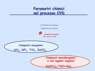
Parametri chimici nel processo CVD Atmosfera di reazione Superficie di crescita Composti precursori Gas, liquidi o solidi Composti inorganici SiH4, WF6, TiCl4, BaNO3.. Composti metallorganici o con leganti organici Ga(CH3)3,Ti(Ot-Bu)3,...
Metal center Ligand CVD Chemical Vapor Deposition y x v z w Substrate u Thermal-CVD Photo Assisted-CVD Plasma Enhanced-CVD uMain flow vDiffusion towards the surface wSurface reaction xByproducts desorption yByproductselimination zNucleation and growth R R R R R R R R
Precursori MOCVD Composti metallorganici o con leganti organici REQUISITI Elevata volatilità Stabilità termica Alta purezza Facile preparazione Dissociazione metallo-legante pulita Decomposizione a temperature relativamente basse
Precursori MOCVD “second generation” M(b-dichet)2.poliammine M(b-chetoimminati)2 Metallo-carbossilati Vantaggi Sintesi “one-pot” Ottima volatilità e stabilità termica Sublimazione quantitativa
Plasma-Enhanced ChemicalVaporDeposition (PE-CVD) and/or RF/Sputtering
combined RF Sputtering CVD/ PE/CVD route Sol-Gel Step 2 Vapor deposition Step 1 Sol-gel matrix (xerogel) porous structure MOx(OH)y M’Oz(guest) MOx(OH)y (host) Outside / Inside nanoclusters Solid solutions Step 3 Thermal treatment tailored dispersion intermixing
- activation of gas-phase species and growth surface - activated species - - infiltration power MOx(OH)ylayer - flexibility processing conditions coverage substrate Plasma processing of xerogel matrices
semiconduttore fino a 400 K LaCoO3 metallo al di sopra di 1200K LaCoO3 (Perovskite) Co (III) Facile accessibilità degli stati di ossidazione II e III La (III) Catodo in SOFCs - stabilità chimica e strutturale - alta conducibilità elettronica - porosità
Step 1: Deposizione sol-gel LaOx(OH)y La(OCH2CH2OCH3)3 + H2O - Struttura porosa - Soluzione etanolica microstruttura (Grazing Incidence-XRD) Composizione chimica (XPS) dip-coating (su SiO2)
Co-O Co-O-La La-OH Step 2 Chemical Vapor deposition (CVD) Co(dpm)2 (dpmH: 2,2-6,6-tetrametil-3,5-eptandione) 110°C O2 350°C CVD flow rate = 150 sccm Ptot = 10 mbar
XPS - profilo di profondità as-grown Co-La intermixing Co-rich La-rich 80 60 O 40 Percentuali atomiche (%) Si 20 La Co 0 0 50 100 150 200 Tempo di erosione (min)
XPS - profilo di profondità 800°C-annealed sample (5h) Distribuzione più uniforme di cobalto e lantanio O La atomic concentration (%) Co Si etching time (min)
GIXRD Jinc = 1.5° Annealing temperature and time influence… (I) (II) (III) (IV) • annealing @ 700°C, t≥8h LaCoO3 decomposition • 700°C, 2h LaCoO3 (I, II, III, IV) • T≥400°C Co3O4(*) + LaOF(◊) 700°C,2h Intensity (a.u.) 600°C,8h ◊ ◊ 400°C,2h * ◊ ◊ as-grown 20 25 30 35 40 45 50 55 2J (degrees) Nanocrystallites Ø = 7÷17 nm
XPS Intermixing La-Co as-grown 60 O F Si 40 atomic % La 20 Co 0 20 40 60 80 100 depth (nm) Surface: %La >> %Co Intermixing Co La [La]/[Co]≈1 after annealing no F signals SIMS Cs+, 14.5 keV 700°C, 2h O 60 O 105 Si 104 40 La Co 103 La atomic % Intensity (c/s) Si Co 20 102 F 101 0 100 20 40 60 80 100 120 20 40 60 80 100 120 depth (nm) depth (nm)
AFM globular grains • homogeneopus surface • Ø = f(temperature,time) 50-180 nm 700°C, 2h 700°C, 2h TEM • double-layer structure • morphology EDS: [La]/[Co] ≈ 1 LaCoO3 SiO2
Case studies Guest phase Side-view few nm Host matrix RF sputtering t = 10’, T=60°C Arplasma, 10 sccm; 0.080 -0.380 mbar, 5 – 35 W Au Au/TiO2 CeO2/ZrO2 LaCoO3 CeO2 PE-CVD from Ce(dpm)4 T = 200°C, t = 10’, 30’, 60’ ((Ar/O2) = 20/5 sccm; 40 W; 1.5 mbar LaOx CVD from La(hfa)3.diglyme T = 200°C, t = 50’ Φ(O2+H2O)/Φ(N2)=3 Ti(iPrO)4+ HAcac in EtOH TiOx(OA)y Sol-gel ZrOx(OA)y sol-gel Zr(OBut)4 in EtOH CoOx(OA)y sol-gel Co(CH3COO)2·4H2O in MeOH
Au/TiO2 - Catalysis and photocatalysis Grätzel cells - Non-linear optics Guest phase (Au) Side-view few nm Host matrix (TiO2) Size effects Interfacial phenomena Soft preparative strategies Nanocomposites with tailored properties Metal particle dispersion Metal-oxide interactions Au-based nanosystems
as-grown Au TiO2 GIXRD SiO2 Jinc = 1.5° set 1 set 2 set 3 annealing in air 0.380 mbar 5 W, 20’ 0.080 mbar 5 W, 10’ 0.380 mbar 25 W, 10’ T (°C) 200 400 600 set 3 Au (111) set 1 600°C 14 set 2 Au (200) 12 set 3 TiO2 (101) TiO2 (200) 10 d (nm) 8 6 4 as-grown 100 200 300 400 500 600 20 25 30 35 40 45 50 2J (°) T (°C) -250 -305 -550 Vbias (V)
600°C set 3 as-grown 40 lp 630 nm 600°C 600°C Absorbance (a.u.) as-grown 30 % Au 20 as-grown 10 450 500 550 600 650 700 750 800 l (nm) 0 0 10 20 30 40 depth (nm) Au penetration
set 2 Au 0.080 mbar 5 W, 10’ TiO2 TEM SiO2 TiO2anatase multi-domain particles annealing at 600°C
Why CeO2/ZrO2 Nanocomposite systems ? Interest Solid oxide fuel cells (SOFCs) automotive three-way catalysts (TWCs) Rh NOx N2 Pt, Pd CO, HC CO2 + H2O • higher thermal stability • improved redox properties Ceria OSC (Oxygen Storage Capacity) Ce(IV) Ce(III) Al2O3 / CexZr1-xO2/ NM (Pt, Pd, Rh) • free noble metal processing • defective nanocomposites
CeO2(PE-CVD)/ZrO2(SG) annealing in air t = 30’ t = 60’ T (°C) 600 900 q ZrO2 q 8 q CeO2 8 8 8 q q 8 8 q q 8 900°C 600°C as-grown 25 30 35 40 45 50 55 J 2 (°) peak shift (≈ 0.2 ) with respect to ZrO2 positions ....solid solution? • Zirconia crystallization above 600°C • Nanocomposite systems 5÷13 nm
TEM SAED t = 60’ 900°C Formation of a Ce-Zr-O ternary phase Grain coarsening t = 60’ 600°C Co-presence of CeO2 e ZrO2 Uniform dispersion of CeO2 on ZrO2
CeO2(PE-CVD)/ZrO2(SG) XPS 40 as-grown Ce 30 Zr Si 20 atomic percentage (%) 10 0 30 0 40 80 120 900°C Zr sputtering time (min) Si 20 atomic percentage (%) Ce 10 0 0 40 80 120 160 sputtering time (min) t = 60’ • In-depth Ce penetration already at 200°C! porous matrix, plasma action • More homogeneous distribution • Similar Ce andZrprofiles ….Ce0.3Zr0.7O2 ?