Download
1 / 29
290 likes | 378 Views
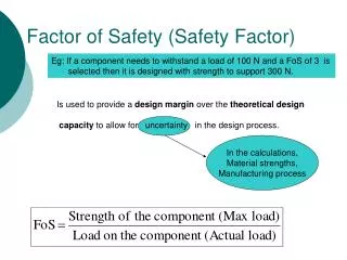
Understand the indicators of failure in machine parts due to static loading and how factor of safety assessments ensure part adequacy. Learn about brittle vs. ductile materials, strength vs. stress assessments, and applying factor of safety for various performance measures.

E N D
FACTOR OF SAFETY INDICATORS OF FAILURE STATIC LOADING
INDICATORS OF FAILURESTATIC LOADING • Failure of a machine part in static loading may be indicated by one of three events: • Ductile material yielding because induced stress has reached yield strength • Brittle material fracture because induced stress has reached ultimate strength • Excessive deflection of part causing loss of function, including slender column where the deflection causes elastic instability and buckling
BRITTLE VERSUS DUCTILE MATERIAL • A rough guide employs percent elongation at fracture obtained from the tensile test of the material • Brittle materials have Percent Elongation<5% • Ductile materials have Percent Elongation > 5%
FACTOR OF SAFETY AND ASSESSMENT OF ADEQUACY • Design considerations (or factors) for a machine or structural part are factors or variables that are expected to influence the part’s performance of its intended function. • Such considerations or factors include
Design Considerations/Factors • Ability to perform function • Strength/ stress • Deflection/rigidity • Wear/resistance to indentation • Corrosion resistance • Manufacturability • Reliability • Maintainability e.t.c
Adequacy without Waste • Design seeks to ensure that the factors or considerations are enough, (adequate but not wasteful). • Assessing the part for adequacy with respect to a particular consideration consists of • Determining the indicator value of consideration for part, • Determining the margin by which that indicator value is exceeded. • Example: Strength (maximum stress) /Stress
ADEQUACY ASSESSMENT STRENGTH VERSUS STRESS • Various indicators of strength which may be used are • Tensile strength, • Yield strength, • Fatigue strength etc. • The indicator of strength to be applied will depend on the material and the type of load (static or variable) • A stress expected to cause failure is identified as significant, and this stress may be • Tensile stress, • Shear stress, • Principal stress, • Von-Mises stress, etc
ADEQUACY ASSESSMENT STRENGTH VERSUS STRESS • A particular location of the part is identified as the location where failure is expected to occur • The pair of strength and significant stress selected is compared at this location. • Adequacy is the margin by which the strength exceeds the significant stress
ADEQUACY ASSESSMENT STRENGTH VERSUS STRESS • Adequacy therefore depends on how accurately the strength and significant stress are known, • Adequacy also depends on what margin between strength and stress is enough
ADEQUACY ASSESSMENT FACTOR OF SAFETY • The adequacy of the part with respect to strength can therefore be assessed by comparing the strength of the part to the stress induced at the chosen location of the part • When the strength and stress are compared by dividing the strength by the stress, the adequacy assessment is referred to as the factor of safety, or design factor.
FACTOR OF SAFETYBEFORE DESIGN • When design starts with a material of known strength, the next step is to choose geometry and dimension of the part that is able to carry the object load. • A factor of safety therefore identifies an allowable stress, or design stress that is used to determine required dimension for the part. • The allowable stress is the strength divided by the factor of safety.
FACTOR OF SAFETYAFTER DESIGN • Where the design is complete, the actualfactor of safety is determined by • Comparing the strength of the part, with the stress induced when the part of known geometry and dimension is subject to the object load. • Design can therefore be done through trial and error by determining stress for various dimensions.
FACTOR OF SAFETY • APPLIED ON OTHER MEASURES OR INDICATORS OF LOSS OF FUNCTION • Deflection • Wear
DEFLECTION AND BUCKLING • The concept of factor of safety can be generalized and applied to other indicators that signify loss of function for the part, such as load and deflection. • A slender column subject to compression will fail by buckling, and the loss of function is therefore signified by the buckling load, rather than the compressive strength. • The buckling load can therefore be used as the indicator of loss of function, that is compared with expected load to obtain a factor of safety for the column.
FAILURE BY DEFLECTION • In the case where failure is indicated by a deflection that causes loss of function • Loss of function deflection can be used for comparison with the expected deflection, and a factor of safety obtained to assess adequacy. • This may be the case for a beam with transverse load such as a gear shaft
FAILURE BY WEAR • What if the loss of function occurs as a result surface failure in fatigue caused by contact stresses? • The consequence of failure, in this case, is seen as wear of the surface after several load applications. • A limit for the wear of the part can then be specified in terms of a life (number of load applications) before the limiting level of wear occurs.
FAILURE BY WEAR • A load that will give the desired life can then be chosen as the safe load, since a greater load will reduce the life. • Loss of function from wear is a gradual occurrence and the specification of life therefore answers the question of what is the margin between loss of function load and the operating load.
SELECTING THE FACTOR OF SAFETY • Variables that influence the selection of the factor of safety are: • Material property used as the indicator of loss of function such as strength, loss of function load, loss of function deflection etc, and its variation or uncertainty • Expected variation or uncertainty in the final dimensions of the part, which cannot be controlled by design, because it is in the manufacturing process • Uncertainty resulting from assumptions employed in the design analysis as a means of predicting stress and deflection from the load applied
CHOOSING THE MAGNITUDE OF THE FACTOR OF SAFETY • One of the major factors influencing the magnitude of the factor of safety to be employed in design is the expected consequence of failure. • Consequences of failure can be classified in categories such as: • Inconvenience • Loss of time • Financial loss • Loss of life
CODES OF PRACTICE AND REGULATIONS • When product failure is likely to cause loss of life, codes of practice are developed as part of national and international standards to prescribe the factor of safety that will prevent failure and therefore loss of life. • Examples of such codes of practice and standards are available for design of pressure vessels and boilers • In such standards, the material to be used, the material properties, and the allowable stresses are specified, and hence the factor of safety is specified.
FACTOR OF SAFETY FOR MACHINE PARTS • For other machine parts that are not subject to codes and regulations, the designer is free to choose the factor of safety • This is done by considering the material concerned and the mode of failure expected.
CAST IRON STATIC LOADING • The indicator of failure is ultimate tensile or compressive strength • Failure is expected to occur when the tensile or compressive stress reaches the ultimate tensile or compressive strength at any location • Material is not as homogeneous as steel and often carries residual stresses from the casting process • A value of 3 to 5 is recommended for factor of safety on tensile or compressivestrength
DUCTILE MATERIALS (STEEL) STATIC LOADING • The indicator of failure is yield strength • Failure is expected to occur when the tensile or compressive stress reaches the tensile or compressive yield strength at any location • A value of 1.5 to 2 is recommended for factor of safety to be applied on the yield strength in tension or compression
DUCTILE MATERIALS (STEEL) VARIABLE LOADING • The indicator of failure is endurance or fatigue strength • Fatigue failure depends on both the magnitude of stress and the number of loading cycles • Fatigue strength also varies with material properties as well as other factors that are unique to the part such as: • Yield strength • Stress concentration • Surface finish • Size • Temperature of part
DUCTILE MATERIALS (STEEL) VARIABLE LOADING • Fatigue failure is sudden and total, and occurs in a similar manner to the static failure of brittle materials • A value of 1.3 to 1.5 is recommended for factor of safety to be applied on the fatigue strength
COLUMN FAILURE BY BUCKLING • Members loaded in compression are likely to fail by buckling • Buckling is caused by elastic instability which results in large deflection of the compression member • Buckling load depends on • Yield strength of the material • Modulus of elasticity of the material • End conditions for the column, such as fixed/fixed, pivoted/pivoted, free/fixed, pivoted/fixed. • Compressive load
COLUMN FAILURE BY BUCKLING • A factor of safety of 3 to 6 is recommended to be applied on the buckling load • For a given column dimension and end conditions, the Euler column formula expresses the critical unit load in terms of the slenderness ratio, the modulus of elasticity, and the end conditions constant. • The critical unit load expresses the loss of function load on which the factor of safety is to be applied.
PARTS SUBJECT TO CONTACT STRESSES • Parts such as cams, gear teeth, bearings, rail wheel on rail, are subject to contact stresses between the surfaces which result in local failure of the surface by pitting. • This is local failure caused by contact stress reaching endurance strength of the surface material at the point of contact. • Such local failure does not render the entire machine element out of operation. Pitting is therefore a form of wear since the machine element continues to operate. • A factor of safety of 1.8 to 2.5 is recommended to be applied on the surface endurance strength.