Download
1 / 53
540 likes | 949 Views
Mechanics of Materials II. UET, Taxila Lecture No. (6). Cylinders & Pressure vessels. Cylindrical or spherical pressure vessels are commonly used in industry to carry both liquids and gases under pressure. . Classification of applications.

E N D
Mechanics of Materials II UET, Taxila Lecture No. (6)
Cylinders & Pressure vessels Cylindrical or spherical pressure vessels are commonly used in industry to carry both liquids and gases under pressure.
Classification of applications Cylinders find many applications, two of the most common categories being : a- fluid containers such as : pressure vessels, hydraulic cylinders, gun barrels, pipes, boilers and tanks. b- interference-fitted bearing bushes, sleeves and the like.
Other applications Cylinders can act as beams or shafts eg. ( load building blocks) but in the present chapter cylinders are loaded primarily by internal and external pressures due to adjacent fluids or to contacting cylindrical surfaces.
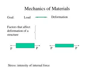
Pressure Loading When the pressure vessel is exposed to this pressure, the material comprising the vessel is subjected to pressure loading, and hence stresses, from all directions.
Factors that affect stresses The normal stresses resulting from this pressure are function of : 1- the radius of the element under consideration, 2- the shape of the pressure vessel (i.e., open ended cylinder, closed end cylinder, or sphere) 3- theapplied pressure.
Two types of analysis are commonly applied to pressure vessels. The most common method is based on a simple mechanics approach and is applicable to “thin wall” pressure vessels which by definition have a ratio of inner radius (r), to wall thickness (t) of r/t ≥ 10.
The second method is based on elasticity solution and is always applicable regardless of the r/t ratio and can be referred to as the solution for “thick wall” pressure vessels.
Limiting proportions (approx) ThinThick d/t > 20 d/t < 20 t/d < 1/20 t/d > 1/20 t/d < 0.05 t/d > 0.05 Where d = Di = inner diameter t = Cylinder thickness
Thin-Walled Pressure Assumptions Several assumptions are made in this method. 1) Plane sections remain plane 2) r/t ≥ 10 with t being uniform and constant 3) The applied pressure, p, is the gauge pressure (where p is the difference between the absolute pressure and the atmospheric pressure)
4) Material is linear-elastic, isotropic and homogeneous. 5) Stress distributions throughout the wall thickness will not vary 6) Element of interest is remote from the end of the cylinder and other geometric discontinuities. 7) Working fluid has negligible weight.
THIN CYLINDERS AND SHELLS 1- THIN CYLINDERS
Classifications of Cylinders Cylinders are classed as being either : open - in which there is no axial component of wall stress, or closed - in which an axial stress must exist to equilibrate the fluid pressure.
When a thin-walled cylinder is subjected to internal pressure, three mutually perpendicular principal stresses will be set up in the cylinder material.
Types of stresses Namely: 1- The circumferential or hoop stress. 2- The longitudinal stress. 3- The radialstress.
Provided that the ratio of thickness to inside diameter of the cylinder is less than 1/20, it is reasonably accurate to assume that the hoop and longitudinal stresses are constant across the wall thickness.
Also, the magnitude of the radial stress set up is so small in comparison with the hoop and longitudinal stresses that it can be neglected.
This is obviously an approximation since, in practice, it will vary from zero at the outside surface to a value equal to the internal pressure at the inside surface.
For the purpose of the initial derivation of stress formulae it is also assumed that the ends of the cylinder and any riveted joints present have no effect on the stresses produced; in practice they will have an effect and this will be discussed later.
1- Hoop or circumferential stress This is the stress which is set up in resisting the bursting effect of the applied pressure and can be most conveniently treated by considering the equilibrium of half of the cylinder.
It is required to calculate the hoop stress in terms of: Pressure (p) Inner diameter (d) Thickness (t)
Half of a thin cylinder subjected to internal pressure showing the hoop and longitudinal stresses acting on any element in the cylinder surface.
Consider the equilibrium of forces in the x-direction acting on the sectioned cylinder shown in figure 2. It is assumed that the circumferential stress H (or θ( is constant through the thickness of the cylinder.
Using the force equilibrium to derive an equation for hoop stress
Calculating the total force owing to internal pressure Total force on half-cylinder owing to internal pressure
Resisting force owing to hoop stress Total resisting force owing to hoop stressHset up in the cylinder walls= Force =
Longitudinal stress Consider now the cylinder shown in Next Figure. Cross-section of a thin cylinder.
End Section of Cylindrical Thin-Walled PressureVessel Showing Pressure and Internal Axial Stresses
Using the force equilibrium to derive an equation for longitudinal stress
Now consider the equilibrium of forces in the z-direction acting on the part cylinder shown in next figure .
Force owing to internal pressure Total force on the end of the cylinder owing to internal pressure Force on cylinder end : Force =
For equilibrium of forces we need to calculate the End section area
End Section Area The cross-sectional area of the cylinder wall is characterized by the product of its wall thickness and the mean circumference For the thin-wall pressure vessels where D >> t the cylindrical cross-section area may be approximated by pDt.
(a) Change in length The change in length of the cylinder may be determined from the longitudinal strain by neglecting the radial stress.
And change in length = longitudinal strain x original length Then change in length =
(b) Change in diameter As above, the change in diameter may be determined from the strain on a diameter, i.e. the diametral strain.
Now the change in diametermay be found from a consideration of the circumferential change. The stress acting around a circumference is the hoop or circumferential stress H giving rise to the circumferential strain H.