Download
1 / 37
380 likes | 565 Views
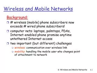
HY436: Mobile Computing and Wireless Networks IEEE802.11. Lecture 5: October 18, 2004 Prof. Maria Papadopouli Assistant Professor Department of Computer Science University of North Carolina at Chapel Hill. Mechanics. Log (in English)

E N D
HY436: Mobile Computing and Wireless NetworksIEEE802.11 Lecture 5: October 18, 2004 Prof. Maria Papadopouli Assistant Professor Department of Computer Science University of North Carolina at Chapel Hill
Mechanics • Log (in English) • Clear problem description for each assignment • Clear description of the format for the generated data • Well-documented code • Another project: • Enhancements, measurements and evaluation of the 2wear-related applications http://2wear.ics.forth.gr
Coordination functions for channel access • Distributed Coordination function • Contention-based access • DIFS ms sensing channel • 4-way handshaking protocol for data transmissions • Backoff process • Point Coordination function • Contention-free access
Using the NAV for virtual carrier sensing Every host that receives the NAV differs the access, even if it is configured to be in a different network
Inter-frame spacing Create different priority levels fro different types of traffic Minimum medium idle time for contention-based services PCF (contention-free) access Preempt any contention-based traffic
A day in the life of an 802.11 Client • Frame Format • Power Management • Security Protocols
A Network of Socialites Our 802.11 station would like to • Join the community (i.e., a network) • Chat for a while (send and receive data) • Take a nap (rest, then wake up) • Take a walk (roam to a new area) • Leave the network
Background • A frame is a chunk of data without control data • A MAC Address MAC Address is a 48-bit permanent ID number on each station in IEEE 802 protocols (e.g.: “00:30:65:01:ed:7e”) • An internet interconnects link-level interconnects link-level physical networks; data transits in physical networks; data transits in packets
Two Modes of Operation of the 802.11 Device • Infrastructure: A special STA, the Access Point (AP), mediates all traffic mediates all traffic • Independent: Stations speak directly to one another
Steps to Join a Network • Discover available networks (aka BSSs) • Select a BSS • Authenticate with the BSS • Associate
Discovering Networks Each AP broadcasts beacons announcing itself Beacon includes: • AP’s MAC address • AP’s clock • Beacon interval (100ms typical) • Network Name (SSID); eg “UNC-1”
Associations • Exclusive: A device can be associated with only one AP • Client-initiated: The device initiates the association process • AP may choose to grant or deny access based on the content of the association request
Reasons to Deny Access • Memory • Traffic load
Networks of Arbitrarily Large size • Chain BSSs together with a backbone network • Several APs in a single area may be connected to a single hub or switch or they can use virtual LAN if the link=layer connection Basic Service Set: the network around one AP APs act as bridges APs are configured to be part of the ESS Backbone network is a layer 2 (link layer) connection
Inter-Access Point Communication • If a client is associated with one AP, all the other APs in the ESS need to learn about that client • If a client associated with an AP sends a frame to a station associated with a different AP, the bridging engine inside the first AP must send the frame over the backbone Ethernet to the second AP so it can be delivered to its ultimate destination • No standardized method for communication Major project in the IEEE802.11 working group the standardization of the IAPP
Infrastructure Mode: Joining a network 1. Discovering Networks (active) • Instead of waiting for beacon, clients can send a probe request which includes • STA MAC address • STA’s supported data rates • May specify a SSID to restrict search • AP replies with proble response frame
Infrastructure Mode: Joining a network 2. Choosing a Network • The user selects from available networks; common criteria: User choice Strongest signal Most-recently used • OS Driver indicates this selection to the STA
Infrastructure Mode: Joining a network 3. Authentication • Open-system ‘authentication’; no password required • Often combined with MAC-address filtering
Infrastructure Mode: Joining a network 3. Authentication • Shared-key ‘ authentication’ called “Wired Equivalency Protection”, WEP
What’s wrong with WEP • Apparent design mistakes make a WEP key recoverable Result 40-bit key on a busy network recoverable in five hours 128-bit key in 15 hours • Improving on WEP without changing STA: • Have lots of keys (e.g., one per user) simultaneously; time to crack increases with number of keys • Change keys frequently
What’s wrong with WEP • 802.1x supports “logging in” to a network, and automatic distribution of WEP data • 802.11i uses 802.1x and adds short-lived keys
Infrastructure Mode: Joining a network 4. Association • Station requests association with one AP • Request includes includes • STA MAC address, • AP MAC address, • SSID (Network name), • Supported data rates, • Listen Interval (described later)
We have now joined the network … • Next: sending data
Sending a frame • Request to Send – Clear to send Used to reserve the full coverage areas of both sender and receiver • Send frame • Get acknowledgement
Infrastructure mode: Sending Data 1. RTS/CTS • RTS announces the intent to send a pkt; it includes: • Sender’s MAC address • Receiver’s MAC address • Duration of reservation (ms) • CTS inidcates that medium is available; includes: • Receiver’s MAC address • Duration of reservation remaining (ms)
Infrastructure mode: Sending Data 2. Transmit frame • Normal ethernet frame has two addresses: sender and receiver • 802.11 data frame has four possible addresses: • Sender (SA) originated the data • Destination (DA): should ultimately receive the data • Receiver (RA): receives the transmission from the sender • Transmitter (TA) transmits the frame • Data frame includes also • Duration remaining in fragment burst • More-fragments ? Indicator • Data
Frame Control Field Indicates if the device is sleeping AP indicates that there are more data available and is addressed to a dozing station
Data sent … • Next: Take a nap
Power Savings: Basic Principle • Whenever a wireless node has noting to send or receive it should fall asleep: turn off the MAC processor, the base-band processor, and RF amplifier to save energy • Easy in an infrastructure wireless network • APs responsible for timing synchronization (through beacons)
Infrastructure mode: Saving Power • STA indicates power management mode is on to AP and waking interval • STA goes to sleep (turns off radio) • STA wakes later; Listens for traffic conditions (e.g., first 10ms of the beacon interval) • STA may request buffered frames • AP sends buffered frames Steps 2-5 repeat
1. STA indicates • Most frames include power-management (PM) bit; PM=1 means STA is sleeping • STA also indicates Listen Interval; length of its naps (in beacon intervals) • Tradeoffs: • Higher listen interval requires more AP memory for buffering • Interactivity issues • APs may use this feature to estimate the resources that will be required and may refuse resource-intensive associations
Infrastructure Mode2. Check for waiting traffic • Station wakes to listen for a beacon, which includes the Traffic-Indication Map (TIM) • TIM is 2,007-bit-long map; • TIM[j]=1 means that station with Associated ID=j has traffic buffered
Infrastructure Mode3. Get buffered traffic • Station sends Power-Saving-Poll to indicate that it is awake and listening • AP sends buffered packets • Station stays awake until it has retrieved all buffered packets
Infrastructure Mode: RoamingRe-association • When a station leaves one BSS and enters another BSS, it can re-associate with its new AP • Re-association request is like association plus: • Previous AP MAC address • Old association id • New AP can contact old AP to get buffered frames
Infrastructure mode: Leaving the network • If a station is inactive, AP may disassociate it automatically; 30 seconds is typical • Station may indicate its de-association politely
Polling-based (centralized) Point Coordination Function (PCF) TDMA scheme • Point-coordinator cyclically polls all stations which are assigned to the network and added to the PC polling table • Assign a time slot to them in which they are exclusively allowed to send data • Drawbacks: Higher bandwidth waste under normal load • Correction (for reducing overhead for polling idle stations) • Embedded Round Robin: dynamic classification of stations as busy or clear