Download
1 / 16
160 likes | 175 Views
This project proposes Offset Variable Pulse Width Modulation for controlling smart device flash lights, improving BER performance.

E N D
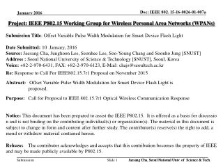
Project: IEEE P802.15 Working Group for Wireless Personal Area Networks (WPANs) Submission Title: Offset Variable Pulse Width Modulation for Smart Device Flash Light Date Submitted: 10 January, 2016 Source:Jaesang Cha, Junghoon Lee, Seonhee Lee, Soo-Young Chang and Soonho Jung [SNUST] Address : Seoul National University of Science & Technology [SNUST], Seoul, Korea Voice: +82-2-970-6431, FAX: +82-2-970-6123, E-Mail: chajs@seoultech.ac.kr Re: Response to Call For IEEE802.15.7r1 Proposal on November 2015 Abstract: Offset Variable Pulse Width Modulation for Smart Device Flash Light is proposed. Purpose: Call for Proposal to IEEE 802.15.7r1 Optical Wireless Communication Response Notice: This document has been prepared to assist the IEEE P802.15. It is offered as a basis for discussion and is not binding on the contributing individual(s) or organization(s). The material in this document is subject to change in form and content after further study. The contributor(s) reserve(s) the right to add, amend or withdraw material contained herein. Release: The contributor acknowledges and accepts that this contribution becomes the property of IEEE and may be made publicly available by P802.15. Jaesang Cha, Seoul National Univ. of Science & Tech. Slide 1
Contents • Introduction • App. based Smart Device Light(Flash, etc.) Control • Comparison App. based Flash Light control with HW Modem based Light control • Offset-VPWM • BER Performance • Conclusion Jaesang Cha, Seoul National Univ. of Science&Tech
Introduction (1) • Smart Device Light (Flash, etc.) based OWC Another Device Camera Smart Device Camera Smart Device (App based Tx ) Low Speed PD
Introduction (2) • Low rate OWC (such as LED-ID and OCC) can be sent by Device Light and can be received by low rate PD or Camera. • Below picture is an example of Smart Devices. - Left one shows low rate PD communication. - Right one shows Camera communication.
Introduction (3) • Proposed OWC/RF Hybrid mode can access High rate data from cloud by OWC address Pointer(URL, Address etc.) • Hybrid Tx : Smart device Light(Flash, etc.) & RF(3G/LTE, WiFi, Bluetooth etc.) • Hybrid Rx : Smart device Camera & RF(3G/LTE, WiFi, Bluetooth etc.) Cloud Network Link, URL, IP Address, etc Connect by Wi-Fi/BT Camera + RF Smart Device Light + RF - Smart Device Light’s data : OWC IP address Pointer (URL, Storage address etc.) - RF data : High rate based access function to Virtual Cloud Big Data Network(Storages) - Virtual Big data exchange(Flexible IoT solution) is available using Hybrid mode
Introduction (4) • Authentication using Smart-Device Light and Camera • LBS using Smart-Device Light(using Offset-VPWM) and Camera LED Light Gateway (Camera) Smart Device Smart Device (LBS)
App. based Smart Device Light Control(1) DLT <SW structure of Smart Device + Flash Light Tx App. > <SW structure of Smart Device > • Proposed scheme is App. based Device Light system without HW change Just have only to add(install) “Device light transmitter(DLT)” App.
App. based Device Light Control(2) Device Light(Flash, etc.) control App. : Light on/off control by calling framework IO Main control block for Device light control App. (Application) Frame Work (Light IO IF) Device Light IO interface : Calling Devie Light driver SW Kernel layer (S/W Driver) Flash Light IO interface : On/Off Control of device Flash device, etc. HW Turn on or off light • App. is main control block for Device Light(Flash, etc.) control
Comparison App. based Flash Light control with HW Modem based Light control(1) • HW modem based light control system can turn on/off light at absolutely exact time duration due to HW clock synchronization • App. based light control can’t keep turning on/off timing because it is performed by CPU
Comparison App. based Flash Light control with HW Modem based Light control(2) Exact time span HW modem based light control Jitter @ rising edge Jitter @ falling edge App. based Flash light control • App. based Flash control can’t keep exact on/off timing when context switching process, ISR(interrupt service routine), and so on… • It can happen both rising and falling edge time
Offset-VPWM (1) • In order to overcome Jitter problem, we propose new modulation scheme Offset-VPWM(Variable Pulse Width Modulation) • In Offset-VPWM, Data is expressed with offset pulse width For example, 2bits data were mapped into 4 Offset-VPWM symbol as below < Mapping Table> < Offset-VPWM scheme>
Offset-VPWM (2) • Even though rising edge jitter happened, receiver can synchronize rising edge and check pulse width length
Offset-VPWM (3) • If falling edge jitter happened, it can affect BER performance • For example,When sending ’00’, If Tx signals falling edge happened with short pulse width(v) then Rx’s decision making error is occurred (00 01) Jitter @ falling edge P 0 0 00 01 v 0 1 • Efficient offset value design is needed considering the relation falling jitter and pulse width
BER Performance(1) • P is 40ms* • Falling edge is varied from 0%~5% of P • Offset length(v) is varied from 10~50% of P <Simulation Parameters> < Offset-VPWM scheme> *P value 40ms is calculated via (1second) / (the number of flash blinking) The number of blinking is the capacity how often mobile device can turn flash on and off means that the frequency which was tested using Nexus5S device.
BER Performance(2) <Pulse offset length 10% of P> <Pulse offset length 20% of P> <Pulse offset length 30% of P> <Pulse offset length 40% of P> <Pulse offset length 50% of P>
Conclusions • Offset Variable Pulse Width Modulation for Smart Device Light(Flash, etc.) are proposed • Proposed scheme is App. based Device Light system without HW change Just have only to add(install) “Device light transmitter(DLT)” App. • Offset-VPWM can be applied on LED-ID and OCC • Application scenarios like OWC/RF Hybrid method, Authentication, LBS were introduced • Smart Device based/connected Multiple Device Lights also can be applied Jaesang Cha, Seoul National Univ. of Science&Tech.


