html5-img
1 / 56

SLAC Aerial View

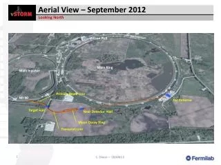
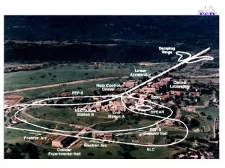
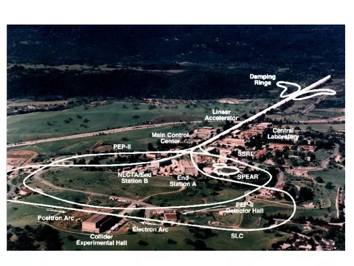
SLAC Aerial View. SLAC Timing System Specifications. Blue Book: (~1968) Resolution: 50 nSec - Jitter: 15 nSec - Main Trigger Line Waveform: + / - 400 Volts. PEP – II: (~1998) - Resolution: 2.1 nSec - Jitter: 20 pSec - NIM Level Waveform:

lavonn
Download Presentation

SLAC Aerial View

An Image/Link below is provided (as is) to download presentation Download Policy: Content on the Website is provided to you AS IS for your information and personal use and may not be sold / licensed / shared on other websites without getting consent from its author. Content is provided to you AS IS for your information and personal use only. Download presentation by click this link. While downloading, if for some reason you are not able to download a presentation, the publisher may have deleted the file from their server. During download, if you can't get a presentation, the file might be deleted by the publisher.

E N D

Presentation Transcript


  1. SLAC Aerial View

  2. SLAC Timing System Specifications • Blue Book: • (~1968) • Resolution: 50 nSec • - Jitter: 15 nSec • - Main Trigger Line • Waveform: • + / - 400 Volts PEP – II: (~1998) - Resolution: 2.1 nSec - Jitter: 20 pSec - NIM Level Waveform: 0 to –0.7 V into 50 Ohms

  3. Historical MCC Timing Units

  4. Machine Cycle 1 / 360 Second = 2.78 mSec

  5. Timing System Enclosure

  6. Waveforms: 476 MHz with FIDUCIALS LINAC PEP - 2

  7. Waveforms: 119 MHz and NIM Pulse FIDO Output PDU Output

  8. SLAC Landscape

  9. Trigger Generation, simplified

  10. Sector 0 Trigger Generation, oversimplified

  11. Trigger Generation, simplified

  12. Area Three, Rack One

  13. Area One, Rack One CAMAC

  14. Trigger Distribution: Sector 0 and 1

  15. Klystron Gallery

  16. Trigger Distribution: Damping Rings

  17. LINAC Rack, Front

  18. LINAC Rack, Rear

  19. MDL Coupled Output

  20. LINAC Timing Sector TEN

  21. LINAC Timing Diagnostic

  22. Fiber Optic Xmtr

  23. Fiber Optic Link

  24. NLCTA Trigger Distribution

  25. NLCTA Triggers

  26. NLCTA Beam Line

  27. PEP – 2 Timing Generation

  28. PEP – 2 Timing Equipment

  29. PEP – 2 Timing Distribution

  30. PEP – 2 Klystrons

  31. SLC Timing Distribution

  32. Bldg 136 Trigger Distribution

  33. 119 MHz Propagation in SLC Sector 30 “Source” Final Focus

  34. FIDO PDU (SLC) PDU (PEP – 2) Simple Timing Buffer VDU 476 MHz Distribution 119 MHz Distribution PEP – 2 Timing Phase Lock and Distribution Some Timing Modules

  35. FIDO Unit

  36. FIDO B. D.

  37. PDU – SLC Style Sixteen channels per PDU; One channel shown

  38. LINAC Timed Crate

  39. PDU, Backplane, and STB Counters Drivers

  40. PEP – 2 Timed Crate

  41. Vernier Delay Unit

  42. 476 Distribution Unit

  43. 476 MHz Distribution B.D.

  44. FIDOs and 119 Distribution

  45. 119 MHz Distribution B.D.

  46. TPLD Chassis Front Panel

  47. Timing Phase Lock Distribution B.D. Graphic by E.L.Cisneros

  48. TPLD SCP Diagnostics 1

  49. TPLD SCP Diagnostics 2

  50. Kickers Single Beam Dumper Logic Beam Position Monitors Toroid Charge Monitors Trigger Gate and Synchronizer Some Triggered Devices

More Related