Download
1 / 21
430 likes | 970 Views
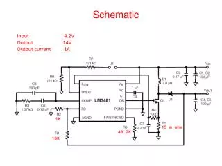
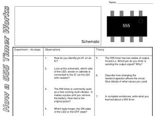
20.1 Schematic Diagrams and Circuits. p730 - 735. Essential Questions. How does the wiring in a circuit change its ability to supply power to devices? How do we represent physical circuit elements in schematic drawings?. Objective(s ): We will be able to….

E N D
20.1 Schematic Diagrams and Circuits p730 - 735
Essential Questions • How does the wiring in a circuit change its ability to supply power to devices? • How do we represent physical circuit elements in schematic drawings?
Objective(s): We will be able to… • Interpret and construct circuit diagrams. • Identify circuits as open or closed. • Deduce the potential difference across the circuit load, given the potential difference across the battery’s terminals.
Agenda: • Warm-Up • Recap what happened on Friday. • Reminder: Chapter 19 Test Tomorrow. • Introduction to Circuit Diagrams • Notes: • Schematic Diagrams • Circuits and short circuits • EMFs
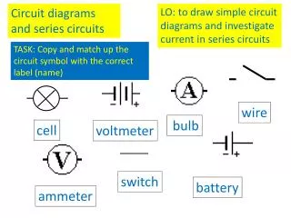
Warm Up • The following drawings are used in circuit diagrams. List what you think each object represents. • Battery/DC Source • Switch • Capacitor • Wire • Resistor • Light Bulb • Plug
Schematic Diagrams • A diagram that is used to represent the construction of an electrical apparatus is a schematic diagram. Sometimes called a circuit diagram. • They are used to determine how parts in an electrical device are arranged, and to help understand how they work.
Schematic Diagram Symbols • Wire or conductor
Schematic Diagram Symbols • Resistor or circuit load (Overall resistance. Discussed more in a minute.)
Schematic Diagram Symbols • Bulb or lamp
Schematic Diagram Symbols • Plug
Schematic Diagram Symbols • Battery
Schematic Diagram Symbols • Switch
Schematic Diagram Symbols • Capacitor
Electric Circuits • An electric circuit is a pathway through which charges can be conducted. • Circuits (and switches) must be closed to complete the pathway, otherwise charges will not flow. Light switch on. • Open circuits conduct no electricity. Light switch off.
Electrical Circuits • All circuits consist of two things… • A source of potential difference (electrical energy), like a battery, and… • A load: an element or group of elements in a circuit that dissipates energy.
Light Bulbs • Light bulbs themselves are a complete circuit with a resistor. • The filament acts as a resistor, converting electrical energy into internal energy and thus heat and light.
Short Circuits • Without a load (bulb or resistor), a circuit has very little resistance. • And therefore, very high current. • This is called a short circuit. • Most wires overheat when they short circuit (think of the battery and the paperclip). DANGEROUS! • This is why we have fuses and circuit breakers.
Electromotive Force (emf) • Literally, the force that moves electrons. • Any device that increases the flow of charge in a circuit is a source of emf, the energy per unit charge supplied by the source. • In real life, the terminal voltage (actual potential difference from the battery) is less than its emfdue to internal resistance. • The amount of power the battery actually supplies is less than what it should, because some of the energy is wasted internally.
Terminal Voltage • The potential difference across a load equals the terminal voltage. • Meaning: if a battery supplies 1.5 volts of potential difference, • then the voltage across the resistor, bulb, or collection of resistors and bulbs etc. is 1.5 volts. • No energy created or destroyed.
Recap • Circuit diagrams are used to represent and analyze the composition of electric devices. • Open circuits do not have a complete pathway, so they do not conduct electricity. Closed circuits complete the pathway, so they do conduct electricity. • The voltage across the load of a circuit is the same as the voltage supplied by the battery.
Homework • Tonight: Finish study guide. • Due Wed: p 735 #1-5