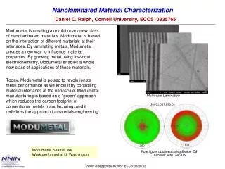
Developing an Infrared Flash Method for Bulk Material Characterization
Developing an Infrared Flash Method for Bulk Material Characterization. Aida Yoguely Cortés- Peña Mentors: Justin Jones & Michael Viens Materials Engineering Branch/Code 541 Goddard Space Flight Center Mechanical Engineering Student Georgia Institute of Technology.

Developing an Infrared Flash Method for Bulk Material Characterization
E N D
Presentation Transcript
Developing an Infrared Flash Method for Bulk Material Characterization Aida Yoguely Cortés-Peña Mentors: Justin Jones & Michael Viens Materials Engineering Branch/Code 541 Goddard Space Flight Center Mechanical Engineering StudentGeorgia Institute of Technology Materials Engineering Branch/Code 541
Outline • Background Non-Destructive Evaluation Infrared Thermography Research Objective • Part 1: Thermal Diffusivity Measurements Angstrom and Parker’s Method for Thermal Diffusivity Sample Preparation Results • Discussion • Part 2: Subsurface Defect Detection Area Fraction Measurement Temperature Line Profile Derivative Image Analysis • Space Center Enrichment Activities • Acknowledgements • References Materials Engineering Branch/Code 541
Non-Destructive Evaluation (NDE) NDE: evaluate properties of a material without altering the article being inspected. X-Ray Radiography (J. Jones) Ultrasound Response for Adhesively Bonded Component (D.Polis) [1]. Infrared Thermography Image of the Orbiter’s heated tiles during re-entry [2]. • Infrared Thermography: • detects radiation in the infrared (IR) range, 1 µm - 20 µm, of the electromagnetic spectrum. • amount of IR radiation increases with temperature [1] "Composite Crew Module: Nondestructive Evaluation Report ." 8 Sep. 2011. NESC-RP-06-019 [2] Roebuck, Kevin. Terahertz Radiation: High-impact Emerging Technology - What You Need to Know: Materials Engineering Branch/Code 541
Infrared Thermography • Infrared energy (thermal energy) directed towards an object is either reflected (ρ), transmitted (τ)through, or absorbed (α). • The intensity of the emitted infrared radiation depends on the material's emissivity (ε). • Emissivity: ability of a surface to emit energy by radiation. • ε = Radiation ability of a target [3] • Black Body Source: absorbs all incident of radiation. ε = 1 • High (0.95) Emissivity Stickers: Used to determine emissivity of an object by adjusting the value until the temperature on both surfaces match. Consists of a hole in a large encloser. Light entering the hole is reflected indefinitely and absorbed inside [4]. [3] "ThermoIMAGER TIM 160 Operators Manual ." MICRO-EPSILON. 25 Jul. 2012. [4] "Black body." 26 Jul. 2012. <http://en.wikipedia.org/wiki/Black_body>. Materials Engineering Branch/Code 541
Infrared Thermography • Applications: • Maintenance of in-service aircraft • Manufacturing of large aerospace structures. • Example: Inspection of the Space Shuttle wing leading edges Reinforced Carbon-Carbon system. Global Precipitation Measurement [5] MagnetosphericMultiscale Mission [6] • Research Objective: • Thermal Diffusivity Measurements: develop an infrared technique for material characterizing of Thermal Diffusivity and Thermal Conductivity. • Subsurface Defect Detection: Develop tools for composite inspections. [5] "GPM Home | Precipitation Measurement Missions." Precipitation Measurement Missions | An international partnership to understand precipitation and its impact on humankind.. N.p., n.d. Web. 26 July 2012. <http://pmm.nasa.gov/GPM>. [6] "MagnetosphericMultiscale (MMS) Mission." MagnetosphericMultiscale (MMS) Mission. N.p., n.d. Web. 26 July 2012. <http://mms.gsfc.nasa.gov/>. Materials Engineering Branch/Code 541
Part 1: Thermal Diffusivity Measurements Materials Engineering Branch/Code 541
Thermal Diffusivity Measurement Techniques Thermal Diffusivity: represents how fast heat diffuses through a material. It is the measure of thermal inertia. K = thermal conductivity ( W M-1K-1) ρ = density (kg m-3) Cp = specific heat capacity (J kg-1K-1) Angstroms Method: The thermal conductivity of a metal rod can be calculated by applying a heat pulse to one end while leaving the other end at room temperature, and measuring the temperature at two points as a function of time [7]. There is a need to reduce the length of time and the size of the sample required to make reliable measurements [8]. [7] Angstrom’s Method of Determining Thermal Conductivity, Andrew M. Bouchard, Physics Department, The College of Wooster, Wooster, Ohio 44691, May 4, 2000 [8] Parker, W. J.; Jenkins, J. J.; Abbott, G. L.; Butler, C. P. J. Appl. Phys. 1961, 32, 1679-1684. Materials Engineering Branch/Code 541 k Heat Conducted m2 α = = ( ) ρ Cp Heat Stored s
Thermal Diffusivity Measurement Techniques • Parker’s Flash Method: A high-intensity short-duration light pulse is absorbed in the front surface of a sample a few millimeters thick, and the resulting temperature history of the rear surface is recorded with an infrared camera [8]. • The thermal diffusivity is determined by the shape of the temperature vs. time curve. L = uniform thickness (cm) t05 = time required for the back surface to reach half of its maximum temperature rise. [8]Parker, W. J.; Jenkins, J. J.; Abbott, G. L.; Butler, C. P. J. Appl. Phys. 1961, 32, 1679-1684. Materials Engineering Branch/Code 541 -1.38 L2 α = π2 t05
Sample Preparation • Epoxies are thermosetting polymers, they irreversibly cures by heat. • In flight hardware, encapsulants are used to avoid degassing. • Stycast 2850 is the most commonly used thermally conductive encapsulant for flight hardware. However, it routinely disbonds during a thermal cycle. • The thermal diffusivity of different epoxy's were measured to find a material that maintains high thermal conductivity with a balance in good bondage strength. • Diameter: 5 cm • Thickness L = 0.1 cm • ∆Temperature = 7 °C- 10 °C • Preparation: • Fill mold with the adhesive. • 24 hour over night stand • 2 hour accelerated cure at 65 °C Collaboration with Cindy Goode and Alejandro Montoya Materials Engineering Branch/Code 541
Results Materials Engineering Branch/Code 541 A B C D
Discussion The Hysol 9309.2 and Arathane 5750 are translucent materials, allowing the IR camera to capture the initial flash, affecting the quality of the thermal diffusivity measurements. To avoid this problem, the specimen should be opaque (non transparent and non translucent) to the pulse of light and to thermal radiation. Future work includes the implementation of a new algorithm to calculate the thermal diffusivity by using the cooling and heating part of the curve to correct for radiative heat loss [7]. [9] Baba T and Ono A 2001 Improvement of the laser flash method to reduce uncertainty in thermal diffusivity measurements Meas. Sci. Technol. 12 (2001) 2046–2057 Materials Engineering Branch/Code 541
Part 2: Subsurface Defect Detection Materials Engineering Branch/Code 541
Image Analysis and Processing:Area Fraction of Delamination • Global Precipitation Measurement (GPM) Solar Array Life Test Pane Life Test Panel • The substrate is a sandwich panel composed of an aluminum honeycomb core coated on the backside, opposite to the solar cells, with white urethane paint. • The paint delaminated the composite and the area fraction of this delamination was assessed. • Delamination: Mode of failure for composite materials in which repeated stresses or impact causes layers to separate. Image of the ply in the visible light spectrum. Collaboration with Dr. Dan Polis Materials Engineering Branch/Code 541
Image Analysis and Processing:Area Fraction of Delamination Total area is the sum of each particle area. IR Image shows presence of delamination. Converted image to a 8-bit image with custom threshold. • Results: • The paint delaminated the composite. • Assessed the area fraction to be ~25% of the first ply. Materials Engineering Branch/Code 541
Image Analysis and Processing:Temperature Line Profile • This composite tube simulates a part of the MagnetosphericMultiscale Mission (MMS) extending arm. • Adhesives of different thicknesses were glued to a smooth surface and a rough surface. • Ultrasound and x-ray inspection detected that the thicker the surface the more debonding. • Using flash thermography, temperature lineprofiles were obtained to identify debonding areas. Collaboration with Dr. Dan Polis Materials Engineering Branch/Code 541 3 3 1 1 2 2 4 4 5 5 Rough Surface Rough Surface Smooth Surface Smooth Surface Thinner Thinner Thicker Thicker
Image Analysis and Processing:Temperature Line Profile Materials Engineering Branch/Code 541 3 1 2 4 5 Rough Surface Smooth Surface Thinner Thicker
Area Fraction Image 05160749.jpg Image of Brazing • Results: • Area fraction 32% Good Braze Outline of Areas Total Area: 0.535 inch^2 Good Braze: Dark Area Converted image to a 8-bit image with custom threshold. Collaboration with YuryFlom Materials Engineering Branch/Code 541
Area Fraction Image 05162234.JPG Image of Brazing Custom Threshold • Results: • Area fraction 47.275% Good Braze Total Area: 0.535 inch^2 Good Braze: Light Area Selection Outline of LOB Areas Collaboration with YuryFlom Materials Engineering Branch/Code 541
Image Analysis and Processing:Visibility Surface Features Without Paint • Aluminum Sheet with embedded numbers. • Captured IR images and searched for number visibility when coated with white paint. • Without paint, poor number visibility • With paint, no number visibility Heating Up Cooling down With White Paint Heating Up Image Subtraction Collaboration with Tim Thomas and Debbie Thomas Materials Engineering Branch/Code 541
Image Analysis and Processing:Video Derivative Composite containing a different materials inside to simulate voids. The location of the defects was identified from the IR images and by processing a video derivative. Materials Engineering Branch/Code 541
Image Analysis and Processing:Video Derivative • Use video derivative for subsurface defect detection Materials Engineering Branch/Code 541
Image Analysis and Processing:Video Derivative Grayscale IR Image. The location of the voids can be seen as the triangle and circular shapes. 1st Derivative Shows the rate at which it is heating up or cooling down. 2nd Derivative: Indicates time at which heat deposited at the surface encounters a subsurface interface. [9] [10] Shepard S.M., “Flash Thermography of Aerospace Composites ”, Fourth Pan American Conference for NDT, October 2007, Buenos Aires, Argentina Materials Engineering Branch/Code 541
Thermographic Signal Reconstruction Technique • Derivative image analysis allows for the reliable measurement of sample thickness, defect depth, and thermal diffusivity. In addition they are unique and invariant to ambience conditions, surface preparation or input energy. • Thermographic Signal Reconstruction (TSR) Technique • Processes several hundred frames of raw data reducing it to a set of equations. • Advanced manipulation, such as obtaining the 2nd derivative, and using it to calculate the local wall thickness or flaw depth. • Inspection of low emissivity surfaces without surface preparation [7]. • Future development of the infrared thermography capabilities includes the implementation of this TSR technique. [10] Shepard S.M., “Flash Thermography of Aerospace Composites ”, Fourth Pan American Conference for NDT, October 2007, Buenos Aires, Argentina Materials Engineering Branch/Code 541
Space Center Enrichment Activities Science Jamboree Tour of building 7 Maryland Space Business Luncheon Goddard Toastmasters Goddard Dance Club Materials Engineering Branch Tour Branch Picnic Goddard Day Intern Open Mic Poster Session Sailing Materials Engineering Branch/Code 541
Acknowledgements • Special thanks to my mentors Justin Jones and MichaleViens for their guidance and support this summer. • Daniel Polis, YuryFlom, Timothy Thomas and Debbie Thomas for allowing me to assist them in their projects. • Alejandro Montoya, Cindy Goode, Dewey Dove, Charles Powers, and Bruno Munoz for helping me acquire and learn to use the tools to setup my experiment. • James Magargee for sharing his research experience and helping me grow in the field. • Code 541 Staff • Jeff Stewart for the Center tour. • Hispanic College Fund and NASA Education staff for the excelent internship program. Materials Engineering Branch/Code 541
Thank You! Materials Engineering Branch/Code 541
References [1] "Composite Crew Module: Nondestructive Evaluation Report ." 8 Sep. 2011. NESC-RP-06-019 [2] "Infrared Astronomy." Cool Cosmos. N.p., n.d. Web. 26 July 2012. <coolcosmos.ipac.caltech.edu/cosmic_classroom/ir_tutorial/what_is_ir.html>. [3] "ThermoIMAGER TIM 160 Operators Manual ." MICRO-EPSILON. 25 Jul. 2012. [4] "Black body." 26 Jul. 2012. <http://en.wikipedia.org/wiki/Black_body>. [5] "GPM Home | Precipitation Measurement Missions." Precipitation Measurement Missions | An international partnership to understand precipitation and its impact on humankind.. N.p., n.d. Web. 26 July 2012. <http://pmm.nasa.gov/GPM>. [6] "MagnetosphericMultiscale (MMS) Mission." MagnetosphericMultiscale (MMS) Mission. N.p., n.d. Web. 26 July 2012. <http://mms.gsfc.nasa.gov/>. [7] Angstrom’s Method of Determining Thermal Conductivity, Andrew M. Bouchard, Physics Department, The College of Wooster, Wooster, Ohio 44691, May 4, 2000 [8]Parker, W. J.; Jenkins, J. J.; Abbott, G. L.; Butler, C. P. J. Appl. Phys. 1961, 32, 1679-1684. [9] Baba T and Ono A 2001 Improvement of the laser flash method to reduce uncertainty in thermal diffusivity measurements Meas. Sci. Technol. 12 (2001) 2046–2057 [10] Shepard S.M., “Flash Thermography of Aerospace Composites ”, Fourth Pan American Conference for NDT, October 2007, Buenos Aires, Argentina <http://www.istec.nl/web/images/uploads/files/thermometer_1/man-thermoimager-tim-en.pdf.pdf>. Materials Engineering Branch/Code 541