Fundamentals of Circuit Theory: AC/DC, Transients, Filters, and Non-Linear Devices
120 likes | 132 Views
Explore the principles of circuit theory including Ohm's Law, transient response, filters, and diodes/transistors. Understand ideal sources, meters, and Linear/Non-Linear components in DC and AC circuits.

Fundamentals of Circuit Theory: AC/DC, Transients, Filters, and Non-Linear Devices
E N D
Presentation Transcript
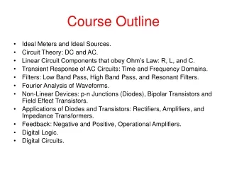
Course Outline • Ideal Meters and Ideal Sources. • Circuit Theory: DC and AC. • Linear Circuit Components that obey Ohm’s Law: R, L, and C. • Transient Response of AC Circuits: Time and Frequency Domains. • Filters: Low Band Pass, High Band Pass, and Resonant Filters. • Fourier Analysis of Waveforms. • Non-Linear Devices: p-n Junctions (Diodes), Bipolar Transistors and Field Effect Transistors. • Applications of Diodes and Transistors: Rectifiers, Amplifiers, and Impedance Transformers. • Feedback: Negative and Positive, Operational Amplifiers. • Digital Logic. • Digital Circuits.
Things we already know • Ohm’s Law: I = V/R or I = V/Z more generally for AC Circuits. • Capacitor: C = Q/V, I = C dV/dt. • Inductor: L = F/I, V = L dI/dt. • Faraday’s Law:V = dF/dt, F = Magnetic Flux. • Power = Current X Voltage; Power = Energy per Unit Time.
Ideal Sources Ideal Voltage sources supply a fixed voltage V independent of the resistance of the load. (i.e., they have zero internal resistance.) However, real voltage sources have an internal non-zero resistance and the voltage delivered depends upon the resistance of the load. Ideal Current sources supply a fixed current I independent of the resistance of the load. (i.e. they have infinite internal resistance.) However, real current sources have a finite parallel (shunt) Internal resistance.
Ideal Meters Ideal Volt Meters have infinite resistance. (i.e. they do not draw current.) Real Volt Meters have a non-zero finite resistance and draw some current. Ideal Ammeters have zero internal resistance. (i.e. when placed in a circuit, they have no voltage drop.) Real Ammeters have a non-zero resistance and will have a voltage drop the meter terminals.
Combination of Batteries and Resistors Want to determine an Equivalent Circuit for a Black Box Consisting of Batteries and Resistors only • We will prove that the most simple Equivalent Circuit is: • A voltage source in series with a resistor. (or) • A Current source in parallel with a resistor.
We measure two quantities with ideal meters: • The open circuit voltage. • The short circuit current. An ideal volt meter draws no current. An ideal ammeter has no resistance.
Two Terminal Black Box Measure Open Circuit Voltage
Two Terminal Black Box Measure Short Circuit Current
Two Terminal Black Box Linear Components so I vs V is a Straight Line The slope defines a Resistance: R = V/I
V V is the Open Circuit Voltage R = I/V I is the Short Circuit Current This is the Thevenin Theorem
A Current Source I is the Short Circuit Current R = I/V V is the Open Circuit Voltage This is the Norton Theorem