Download
1 / 25
260 likes | 404 Views
Subsea Spill Containment GOM Overview of the Helix Fast Response System (HFRS) NAMEPA – 8 August 2013. Who We Are. Helix Energy is a specialty service provider to the offshore energy industry, with a focus on Well Intervention and Robotics business units. IRS Capabilities.

E N D
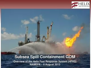
Subsea Spill Containment GOM Overview of the Helix Fast Response System (HFRS)NAMEPA – 8 August 2013
Who We Are Helix Energy is a specialty service provider to the offshore energy industry, with a focus on Well Intervention and Robotics business units.
IRS Capabilities • Light Well Intervention (riser-less) operations • Slickline (mechanical - well maintenance/integrity) • Electricline (electronic - production enhancement/data acquisition/well performance) • Tree Recovery/Deployment • Riser-based Well Intervention for Coiled-tubing operations • Pumping chemical (acidisation (washes)/reservoirstimulation) • Cementing ops (well abandonments) • Circulating (wellbore debris clean-out) • Milling (scale build-up) • Logging and Perforating (high-angle wells) • Well Abandonment/Field Decommissioning • Isolate the reservoir – installation of well barriers(mechanical and cement based plugs) • Remove tree (disconnect flowlines, etc. w/Diver/ROV support) • Remove the wellhead • Removal of facilities (with heavy-lift craneage, Divers/ROVsupport) • MODU Alternative • Deepwater IRS operations • Tophole drilling and well Bore initiation • Well Testing or Clean Up • Open Water Completions
Q4000 – Keystone to Early Response Onsite Operations Static Kill Dynamic Kill BOP recovery • Efficient adaptation betweenoperating modes • Containment • Dynamic Kill • Flaring • Static Kill • RecoveryLMRP/BOP Recovery burn
Helix Producer I – Unique capability • Process Capacity: • 45,000 BOPD • 60,000 BLPD • 80 MMCFD • Lloyd’s Register Classed • BSEE and USCG approved • FPU with quick disconnect side mounted fluid transfer system
Safety Challenges • Oil & Gas in Water • Monitoring of Plume • Isolation of PotableWater System • Constant checking ofseawater inlets forcontamination • Fire Boats for Fire Protection • Air Pollution & Hazardous Area • Lower Explosive Limit (LEL) monitoring • Atmospheric Monitoring Equipment (VOCs) & Carbon Filters • Approval of Electrical Equipment in Hazardous Areas • Flaring Operations • Monitoring of Radiation • Water Curtains from Fire Boats • Flame Retardant Clothing & Deck Restrictions • Hearing Protection
New Regulations • Well Integrity Requirement • Certification of casing & cement program by a PE • Two Independent Barriers during completion need to be certified by PE • Isolate Potential Flow Zones, incorporating API RP 65-2 • Installation, sealing, and locking of casing hangers • Negative test to be performed prior to displacing the kill weight fluids with a lighter fluid. • BOP’s & Control Systems Requirements • BOP inspection & maintenance as per API RP 53 • Blind-shear ram function testing with 3rd party verification • Function testing for auto shear & dead man switch • Minimum requirements for ROV intervention including testing • Training/Certification required for personnel operating BOP equipment
New Regulations • Exploration, Development & Production Plans must be accompanied by information regarding oil spills, including calculations of the worst case discharge (WCD) scenario, details on surface intervention to stop the blowout and estimated time to contract a rig to drill a relief well. • Well Containment Screening Tool (WCST) to be used to evaluate whether a well can be shut in using a capping stack while maintaining wellbore integrity • Oil Spill Response Plan requirements changed along with new criteria for regulatory acceptance. • Well Containment Plans required to be submitted with each well
Helix Fast Response System (HFRS) • Consists of: • The MODU Q4000 and FPU Helix Producer I • 10K Well Cap (Capping Stack) • 90’ Combination Oil / Gas Burner Boom • Offtake and Ontake “QCDC” Disconnectable Systems • Offtake Flexible Riser w/ Buoyancy Modules • Buoyant Offloading Hose • Hawser System Connection to Storage Tanker • Waterspray (Water Curtain) Systems for both Q4000 & HP1
Well Capping Stacks 13 5/8”– 10K – Dual Ram 18 ¾” – 15K – Dual Ram 11
WellCap Arrangement Upper RamPressure Panel Lower RamPressure Panel PDAS Panel High Pressure Regulator ROV Bucket to operate GV1 side outlet choke Low PressureRegulator • FRONT SIDE (UPPER & LOWER RAM PRESSURE PANEL AND PDAS PANEL SIDE)
WellCap Arrangement Subsea Accumulators GV2 Outlet(rupture disk assembly connects here) Subsea Accumulator Isolation Valves GV1 Outlet(vent pipe connects here) • BACK SIDE (Accumulator Bottle & Outlet Side)
WellCap Arrangement Chemical Dispersant & MeOH Injection Panel ROV Pressure Panel SubseaAccumulators ROV Bucket to operate GV2 side outlet choke ROV Panel #2 H4 Connector • RIGHT SIDE (ROV Panel #2 Side
HFRS Storage Buoyant Offloading Hose(480m) Flexible Offtake Riser(1065m) Burner Boom Riser Buoyancy Modules
Incident Command System (ICS) HWCGIMH Incident ManagementHandbook for Source Control
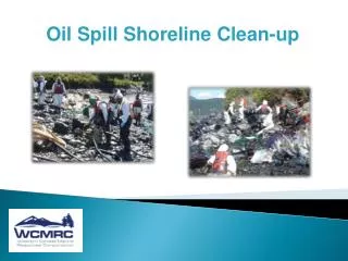
First Response Protocol • Response Schedule • Logistics control for movement of all vessels and aircraft as well as load out and delivery for all equipment & services • Observation and vessel support onsite • Subsea survey and monitoring • Deployment of subsea dispersant delivery equipment • Debris removal (as necessary) • LMRP or BOP Removal (as necessary) • Deployment of subsea dispersants • Mobilization of capping / recovery equipment • Mobilization of deployment vessel • Mobilization of relief well drilling operations • Well Kill & Abandonment
Deepwater Spill Defense Shields Surface Collection & Shore Protection & Relief Well Capping, Containment & Well Kill Control (Blowout Preventer) Prevention Rules, Oversight, Certification, Inspections, Drills, Well Planning, Well Design Engineering and O&G Engineering Standards Application
Deployment Exercise • Well Cap Installed on a Staged Wellhead in 5062 ft. of water • From announcement of drilltill shut-in took just over 7 days.This included 2 days of weatherdelays. • All WellCap functions tested • WellCap hydrostatically tested • Exercise was a success !
Key Strengths of aLocalized First Response System • Immediate and rapid response • Offshore Response Vessels with multiple capabilities • Containment Equipment Ready for Mobilization • Offshore Response Vessel fully crewed, continuously maintained and commercially self-sustaining with continuous operations in the region • Generic response plan can be utilized by all members. • Mutual Aid Recognition for support • Operational Vessels provide the safest, most effective response in the shortest time
Key Strengths Continued • Experienced Personnel are key to effective response • Pre-Planning of Systems and Procedures for emergency response are essential to achieve safe and quick work execution • Coordination and clarity of communication is fundamental to transition operations in high stress working conditions • Maximize onsite vessel functionality & flexibility • All the above facilitate safe simultaneous operations