Download
1 / 28
300 likes | 934 Views
This article elaborates on the design principles and features of the Radiation Safety System for the TPS project at NSRRC. It covers topics such as access control, shielding, redundancy, and reliability to ensure personnel safety in high radiation areas.

E N D
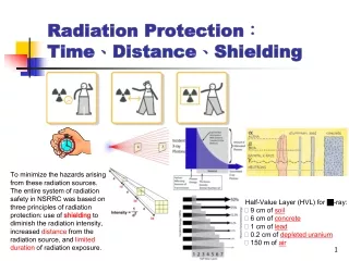
Radiation Protection:Time、Distance、Shielding To minimize the hazards arising from these radiation sources. The entire system of radiation safety in NSRRC was based on three principles of radiation protection: use ofshieldingto diminish the radiation intensity, increased distance from the radiation source, and limited duration of radiation exposure. • Half-Value Layer (HVL) for -ray: • 9 cm of soil • 6 cm of concrete • 1 cm of lead • 0.2 cm of depleted uranium • 150 m of air
Radiation Safety Access Control System for the TPS project Chen, Chien-Rong Radiation & Operation Safety Division, NSRRC Email: ccr@nsrrc.org.tw June 16, 2011
Radiation sources Of the Accelerator Development of an electromagnetic cascade and subsequent photonuclear reaction initiated by a high-energy electron • Kinds of radiation sources originating from the operation of a synchrotron accelerator : • Bremsstrahlung • Neutrons, • Activation • Synchrotron light. Electromagnetic cascade effect High-energy electrons→Bremsstrahlungs γ→Neutrons or Muons→Induced activity
Design Function of Access Control System (ACS) for TPS • The ACS is a sub-system of Radiation Safety System. • The ACS prevents or controls personnel access to and stay at high radiation areas due to the production of prompt radiation. • When the beam is off, prompt radiation is not generated. • The ACS interlock system in this topic refers and pay attention to personnel safety protection, though frequently interlock system is also used for machine (or equipment) protection. • The installations of shielding and safety design must be included. • The system for TPS will be inherited from current TLS system and upgraded. • Our design and implementation will follow the conventions adopted in most facilities and also the recent recommendations of ANSI N43.1 standards entitled “Radiation Safety for the Design and Operation of Particle Accelerators” [2007].
The Radiation Safety System Design Principles for ACS • Diversity :Each safety interlock must function independently of any other safety interlocks. It is generally accepted that when using two identical devices in a redundant configuration the probability of both failing (to ‘danger’) is less than that of a single device. • Redundancy : The ACS is duplicated throughout (input devices, wiring, logic function, outputs), and is periodically tested to ensure that both ‘guard-lines’ are operating correctly. • Reliability :It should provide the required protection, while subject to all foreseeable aging and environmental conditions at the accelerator facility. These conditions may include weather extremes, high electromagnetic fields, high radiation fields, earthquakes, and the cumulative effects of aging on components, such as corrosion, dirt, and normal wear. • Testable :Before commission, the system or sub-system shall be checked and assurance to meet the requirements. Pre-test and on line test is necessary. • Fail Safe :In case of failure, the ACS shall maintain a safe condition. • Expansibility :The expansion and extension shall be reserved. • Configuration- control (revising and modify control)
The Functional Structureand Specification of ACS • When the secure area is opened or ACS is break down, beam should be off and machine must be shut down. • The ACS usually incorporate an extensive network of sensors (such as switches), signal distribution (wiring), logic, and outputs to numerous controlled devices (such as beam inhibiting devices and door locks). • All entrances into high radiation areas or rooms must have interlocks. • To control the access of High Radiation Area, the keys and combination are used.
Implementation of Access Control System • Each safety interlock shall be on a circuit which shall allow it to operate independently of all other safety interlocks. • The caution signs, labels and warning devices around areas of high radiation must be designated. • An audible warming device shall be installed. • An administrative announcement should be given to convey the imminent start of the accelerator or a beamline so that personnel in these areas can recognize that the area is being swept (cleared of personnel) prior to receiving beam. • When a safety interlock system has been tripped, it shall only be possible to resume operation of the accelerator after the condition causing the interrupt has been corrected and reset by hand.
Features of the Radiation Safety System (RSS) • Interlocked-type Access Control System • LINAC, • Booster, storage ring, • Beamlines • Some devices that can generate ionizing radiation not related to the accelerator beam. (e.g. RF power, High electrical voltage, dark current) • The Safety envelope( Shielding, Fence) • Radiation Control System • passive shielding • The interlocked-type Radiation Monitoring System (RMS) • The Operation EnveLop( OEL) • Beamline Radiation Safety System • Optical & Experimental Hutches • Heavy Metal Shutters, Photo Shutters
Controlled Area of ACS The TPS radiation controlled area will be divided into several regions with different levels of access authorizations: free, restricted, prohibited area. An accelerator area will switch between at least two, access conditions: • machine off / no prompt radiation / free access. • machine on / high prompt radiation / personnel exclusion/ prohibited area • Intermediate controlled access state between the 2 conditions above./ restricted, area • The prohibited area of TPS will be divided into five exclusion regions
Operation Status of ACS According to the accelerator operating condition, Accelerator access control status can be divided into • controlled entry/Shut down (Green light), • limited entry/ Patrol inspection (Yellow light) and • prohibited entry/ In operation (Red light)
The Safety Connection of ACS Server (Status Log & Bulletin) Network Integrated PLC Industrial Network Safety PLC Hardwire Interlock Sensors & Devices
Some Importance Design Requirements about the use of Programmable Logic Controllers (PLC) • Programmers shall use the nonvolatile memory. To avoid non-predictable interactions and non- testable condition when multiple applications are installed on a single computer, the more attention is suggested about placing on defense-in-depth against the propagation of common-cause failures within and between functions. • No external interferences, e.g., connection to external network, shall be not allowed. The system shall be completely isolated from such networks, including the World Wide Web. • The revision or upgrade should be controlled and secured. • The redundancy requirements about hardware and software should be achieved. • The both normal and abnormal operation will be considered. • A sufficient Uninterruptible Power Supply (UPS) system shall be provided. The measures to watch program fails shall be taken. • Qualified and safety-rated PLC systems shall be used.
RSS Interlock Logic:Booster/Storage Ring For Single Chain
RSS Interlock Logic: LINAC For Single Chain
Function Diagram of Sub- Access Control System
Structure of Sub-ACS LINAC LINAC Electron Beam LINAC RF System LTB Dipole LTB Beam Stopper Booster/Ring Tunnel RF system Dipole Power Supply Beam Stopper Heavy Metal Shutter Top-Up Interlock Hall Probe (Dipole Setting) Beam stored (e.g. > 150mA) Injection Enable Signal Radiation Monitor
The Layout about the Controlled Enclosures of TPS The prohibited area will be divided into five exclusion regions.
The Listing of TPS Interlock Devices LINAC: LINAC Electron Beam X 2 LINAC RF System X2 LTB Dipole LTB Beam Stopper Booster/Ring Tunnel : RF system Dipole Power Supply Beamline Interlock : Heavy Metal Shutter X48 Beamline Branch Shutter Radiation Monitor X12 Safety and Operation Envelopes : Hall Probe or Dipole Setting Beam Status ( ex. Beam stored > 150mA for Top-up) Beam Current Injection Enable Signal Interlocked doors/gates, Door Keys Emergency off, Forced In/Out Beam Inhibiting or Terminate Device ★ ★ ★ Critical or Injection Device ★ ★ Signal connections between ACS and Interlocked devices (Input)
Thank you for your attention. TPS The End. TLS