Download
1 / 55
550 likes | 711 Views
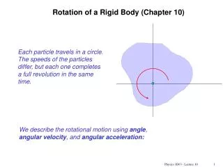
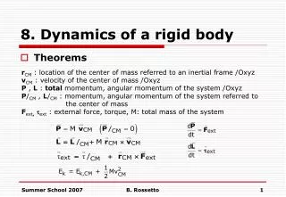
Rigid Body Dynamics chapter 10 continues. around and around we go …. Rotation Axis. Rigid Body Rotation. Moment of Inertia:. CORRESPONDENCE:. Rotational Kinetic Energy.

E N D
Rigid Body Dynamicschapter 10 continues around and around we go …
Rotation Axis Rigid Body Rotation Moment of Inertia:
Rotational Kinetic Energy • We there have an analogy between the kinetic energies associated with linear motion (K = ½ mv 2) and the kinetic energy associated with rotational motion (KR= ½ Iw2) • Rotational kinetic energy is not a new type of energy, the form is different because it is applied to a rotating object • The units of rotational kinetic energy are also Joules (J)
Important Concept:Moment of Inertia • The definition of moment of inertia is • The dimensions of moment of inertia are ML2 and its SI units are kg.m2 • We can calculate the moment of inertia of an object more easily by assuming it is divided into many small volume elements, each of mass Dmi
Moment of Inertia, cont • We can rewrite the expression for I in terms of Dm • With the small volume segment assumption, • If r is constant, the integral can be evaluated with known geometry, otherwise its variation with position must be known
Question – WHAT IS THE MOMENT OF INERTIA OF THIS OBJECT?? WHICH AXIS ?
Two balls with masses M and m are connected by a rigid rod of length L and negligible mass as in Figure P10.22. For an axis perpendicular to the rod, show that the system has the minimum moment of inertia when the axis passes through the center of mass. Show that this moment of inertia is I = L2, where = mM/(m + M).
Remember the Various Densities • Volumetric Mass Density –> mass per unit volume: r = m / V • Face Mass Density –> mass per unit thickness of a sheet of uniform thickness, t : s = rt • Linear Mass Density –> mass per unit length of a rod of uniform cross-sectional area: l = m / L = rA
Moment of Inertia of a Uniform Thin Hoop • Since this is a thin hoop, all mass elements are the same distance from the center
Moment of Inertia of a Uniform Rigid Rod • The shaded area has a mass • dm = l dx • Then the moment of inertia is
Moment of Inertia of a Uniform Solid Cylinder • Divide the cylinder into concentric shells with radius r, thickness dr and length L • Then for I dV=L(2prdr)
Parallel-Axis Theorem • In the previous examples, the axis of rotation coincided with the axis of symmetry of the object • For an arbitrary axis, the parallel-axis theorem often simplifies calculations • The theorem states I = ICM + MD 2 • I is about any axis parallel to the axis through the center of mass of the object • ICM is about the axis through the center of mass • D is the distance from the center of mass axis to the arbitrary axis
ri mi L Howcome?? • The new axis is parallel to the old axis of rotation. • Assume that the object rotates about an axis parallel to the z axis. • The new axis is parallel to the original axis. Not in same plane
mi ri L NEW OLD From the top: Center of Mass
Remember the Center of Mass? Since for our problem the sum is ABOUT the center of mass, rCM must be zero
So: ZERO Inew = ICM + ML2 QED
Parallel-Axis Theorem Example • The axis of rotation goes through O • The axis through the center of mass is shown • The moment of inertia about the axis through O would be IO = ICM + MD 2
Moment of Inertia for a Rod Rotating Around One End • The moment of inertia of the rod about its center is • D is ½ L • Therefore,
Many machines employ cams for various purposes, such as opening and closing valves. In Figure P10.29, the cam is a circular disk rotating on a shaft that does not pass through the center of the disk. In the manufacture of the cam, a uniform solid cylinder of radius R is first machined. Then an off-center hole of radius R/2 is drilled, parallel to the axis of the cylinder, and centered at a point a distance R/2 from the center of the cylinder. The cam, of mass M, is then slipped onto the circular shaft and welded into place. What is the kinetic energy of the cam when it is rotating with angular speed about the axis of the
Torque • Torque, t, is the tendency of a force to rotate an object about some axis • Torque is a vector • t = r F sin f = Fd = rXF • F is the force • f is the angle the force makes with the horizontal • d is the moment arm (or lever arm)
More Torqueing • The moment arm, d, is the perpendicular distance from the axis of rotation to a line drawn along the direction of the force • d = r sin Φ
Torque • The horizontal component of F (F cos f) has no tendency to produce a rotation • Torque will have direction • If the turning tendency of the force is counterclockwise, the torque will be positive • If the turning tendency is clockwise, the torque will be negative Right Hand Screw Rule
Net Torque • The force F1 will tend to cause a counterclockwise rotation about O • The force F2 will tend to cause a clockwise rotation about O • St = t1 + t2 = F1d1 – F2d2
Torque vs. Force • Forces can cause a change in linear motion • Described by Newton’s Second Law • Forces can cause a change in rotational motion • The effectiveness of this change depends on the force and the moment arm • The change in rotational motion depends on the torque
Torque Units • The SI units of torque are N.m • Although torque is a force multiplied by a distance, it is very different from work and energy • The units for torque are reported in N.m and not changed to Joules
Torque and Angular Acceleration • Consider a particle of mass m rotating in a circle of radius r under the influence of tangential force Ft • The tangential force provides a tangential acceleration: • Ft = mat • Ftr=matr=m(ar)r=mr2a • t=Ia
More Associations: How about that?
SO? • Worry about concepts. • Don’t worry about too many new “formulas”.
Torque and Angular Acceleration, Extended • Consider the object consists of an infinite number of mass elements dm of infinitesimal size • Each mass element rotates in a circle about the origin, O • Each mass element has a tangential acceleration
Torque and Angular Acceleration, Extended cont. • From Newton’s Second Law • dFt= (dm) at • The torque associated with the force and using the angular acceleration gives • dt = r dFt = atr dm = ar 2dm • Finding the net torque • This becomes St = Ia
Torque and Angular Acceleration, Extended final • This is the same relationship that applied to a particle • The result also applies when the forces have radial components • The line of action of the radial component must pass through the axis of rotation • These components will produce zero torque about the axis
Torque and Angular Acceleration, Wheel Example • The wheel is rotating and so we apply St = Ia • The tension supplies the tangential force • The mass is moving in a straight line, so apply Newton’s Second Law • SFy = may = mg - T
Problem Find the net torque on the wheel in Figure P10.31 about the axle through O if a = 10.0 cm and b = 25.0 cm.
Anudder one An electric motor turns a flywheel through a drive belt that joins a pulley on the motor and a pulley that is rigidly attached to the flywheel, as shown in Figure P10.39. The flywheel is a solid disk with a mass of 80.0 kg and a diameter of 1.25 m. It turns on a frictionless axle. Its pulley has much smaller mass and a radius of 0.230 m. If the tension in the upper (taut) segment of the belt is 135 N and the flywheel has a clockwise angular acceleration of 1.67 rad/s2, find the tension in the lower (slack) segment of the belt.
Torque and Angular Acceleration, Multi-body Ex., 1 • Both masses move in linear directions, so apply Newton’s Second Law • Both pulleys rotate, so apply the torque equation
Torque and Angular Acceleration, Multi-body Ex., 2 • The mg and n forces on each pulley act at the axis of rotation and so supply no torque • Apply the appropriate signs for clockwise and counterclockwise rotations in the torque equations
32. The tires of a 1 500-kg car are 0.600 m in diameter and the coefficients of friction with the road surface are s = 0.800 and k = 0.600. Assuming that the weight is evenly distributed on the four wheels, calculate the maximum torque that can be exerted by the engine on a driving wheel, without spinning the wheel. If you wish, you may assume the car is at rest.
Work in Rotational Motion • Find the work done by F on the object as it rotates through an infinitesimal distance ds = r dq • dW = F.d s = (F sin f) r dq dW = tdq The radial component of F does no work because it is perpendicular to the displacement
Power in Rotational Motion • The rate at which work is being done in a time interval dt is • This is analogous to P = Fv in a linear system
Work-Kinetic Energy Theorem in Rotational Motion • The work-kinetic energy theorem for rotational motion states that the net work done by external forces in rotating a symmetrical rigid object about a fixed axis equals the change in the object’s rotational kinetic energy
Work-Kinetic Energy Theorem, General • The rotational form can be combined with the linear form which indicates the net work done by external forces on an object is the change in its total kinetic energy, which is the sum of the translational and rotational kinetic energies
Energy in an Atwood Machine, Example • The blocks undergo changes in translational kinetic energy and gravitational potential energy • The pulley undergoes a change in rotational kinetic energy
Rolling Object • The red curve shows the path moved by a point on the rim of the object • This path is called a cycloid • The green line shows the path of the center of mass of the object
Pure Rolling Motion • In pure rolling motion, an object rolls without slipping • In such a case, there is a simple relationship between its rotational and translational motions
Rolling Object, Center of Mass • The velocity of the center of mass is • The acceleration of the center of mass is