Download
1 / 37
370 likes | 456 Views
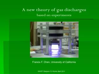
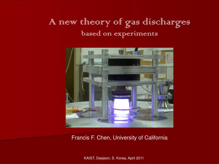
A new theory of gas discharges based on experiments. Francis F. Chen, University of California. KAIST, Daejeon, S. Korea, April 2011. ICPs show anomalous skin depth. Plasma density is peaked on axis even when antenna is on periphery. UCLA. Helicon discharges are also peaked on axis.

E N D
A new theory of gas discharges based on experiments Francis F. Chen, University of California KAIST, Daejeon, S. Korea, April 2011
ICPs show anomalous skin depth Plasma density is peaked on axis even when antenna is on periphery. UCLA
Helicon discharges are also peaked on axis Typical RF deposition profiles are peaked at edge due to the TG mode Typical center-peaked density profile UCLA
FL First solution to skin depth problem Consider the nonlinear effect of the Lorentz force on the motion of an electron in an RF field Eq This force is in the radial direction, while E is in the q direction
UCLA 32000 points
Problem 2: Diffusion across B Classical diffusion predicts slow electron diffusion across B Hence, one would expect the plasma to be negative at the center relative to the edge.
Density profiles are never hollow If ionization is near the boundary, the density should peak at the edge. This is rarely observed.
Consider a discharge of moderate length • Electrons are magnetized; ions are not. • Neglect axial gradients. • Assume Ti << Te UCLA
We now have a simple equilibrium problem Ion fluid equation of motion ionization convection CX collisions neglect B neglect Ti Ion equation of continuity where Result UCLA
Reduce to 1D and normalize ion motion Result ion continuity All radial dependences are kept so far. UCLA
Electrons: short-circuit effect (1) • Assume ionization is higher on the outside (tube 1) • Ions will diffuse inwards, to tube 2 • Electrons can’t follow, but the sheath drop in 2 can increase to trap more electrons to neutralize the ions. • Electrons can effectively “move” across B by the sheath adjustment • THIS SHEATH ADJUSTMENT TAKES ONLY NANOSECONDS UCLA
Electrons: short-circuit effect (2) On a millisecond diffusion time scale… • The sheaths adjust to Maxwellian: is high where n is high (tube 1) • An electric field Er arises to drive ions inwards. • Er is scaled to KTe, so n(r) reaches equilibrium faster than normal. • In equilibrium, n(r) is higher in center, so E is reversed to drive ions out . • Te(r) cannot be changed by short circuit effect. UCLA
The electrons can then follow Boltzmann • The short-circuit effect allows electrons to thermalize across B in nsecs. • Electrons then fall into their most probable distribution: Maxwellian • They then follow the Boltzmann relation everywhere. This is our basic assumption It has amazing consequences! UCLA
3 equations for 3 unknowns: v, n, ion motion ion continuity electron Boltzmann Eliminating n and , we have an ODE for v : UCLA
Matching to Debye sheath is automatic This “plasma solution” has dv/dr as v cs at the sheath edge. All radial variations can be taken into account in this equation. To better see the structure of this equation… Introduce dimensionless variables UCLA
Matching to Debye sheath is automatic This equation yields the profiles of v, n, and Vs in equilibrium UCLA
Properties of this “universal” equation • Plasma properties enter only in k (r ) in the nonlinear u 2 term. • The equilibrium profiles are the same if k is the same. • The neutral density nn does not appear in k. • The profiles are unchanged if the quantities in are changed. • The B-field does not appear. B can be strong or zero. UCLA
Solutions for constant k Let nn and Te be uniform, so k is a constant. Self-similar profiles for 3 values of k Re-scale so a = r /a for one k All profiles are identical for any pressure or tube radius And n (r ) is always peaked on axis, as long as axial losses are negligible. UCLA
No presheath matching is needed Not only are collisions and ionization taken into account everywhere, but Pc(r)’s variation is known since vi is known
Dependence on pressure and Te k is independent of nn, but Pi depends on Te. UCLA
Ionization balance Knowing the ion velocity vs. r, we can calculate the loss of ions from each radial tube. Ionization must replace them in equilibrium. This gives an inverse relation between nn and Te, which depends on radius a. UCLA
Neutral depletion • To keep things simple we have to make some crude approximations. • The n0-n0 mfp is short, so the neutrals diffuse. • Recycling causes uniform input at r = a at all z. • Output at r = a is also uniform because of many bounces before entering pump. UCLA
Neutral depletion (2) At very high density, nn gets very low, and therefore Te is unreasonably high. This is because ENERGY BALANCE has not been considered. To get Te(r), we have to specify the energy input of a specific discharge. UCLA
The EQM code We now have three differential equations: Ion motion, with Maxwellian electrons, in dimensional units Ionization balance at each r Neutral depletion • The EQM code by Curreli solves all three simultaneously for given • Plasma density on axis • Initial neutral density • KTe, either uniform or with given profile UCLA
UCLA We now specify the helicon discharge An antenna launches what is essentially a whistler wave in a DC magnetic field
The HELIC code for helicon discharges The HELIC program for helicons and ICPs can calculate the power deposition Pin(r) for given n(r), Te(r) and nn(r) for various discharge lengths, antenna types, and gases. However, B(z) and n(z) must be uniform. The power lost is given by
Energy balance gives us the data to calculate Te(r) The particle losses Wi and We are simple. The radiation loss Wr, however, has to be calculated from the Vahedi curve, known for argon. This gives the energy needed to create each ionization, including all the radiation that is lost before that happens. Knowing Pin(r), we can calculate KTe from this curve.
Why are helicon discharges such efficient ionizers? The helicon wave couples to an edge cyclotron mode, which is rapidly absorbed.
Density profiles for given Pin profiles These are power deposition profiles for different cases with uniform n(r), from HELIC These are the corresponging density profiles from EQM, using Te(r) from the Vahedi curve. However, Pin (r) was not calculated from n(r). We must iterate. UCLA
Sample of EQM-HELIC iteration It takes only 5-6 iterations before convergence. Note that the Te’s are now more reasonable. Te’s larger than 5 eV reported by others are spurious; their RF compensation of the Langmuir probe was inadequate. UCLA
Comparison with experiment This is a permanent-magnet helicon source with the plasma tube in the external reverse field of a ring magnet. It is not possible to measure radial profiles inside the discharge. We can then dispense with the probe ex-tension and measure downstream. 2 inches UCLA
Probe at Port 1, 6.8 cm below tube • The density peaks on axis • Te shows Trivelpiece-Gould deposition at edge. • Vs(Maxw) is the space potential calc. from n(r) if Boltzmann. UCLA
Dip at high-B shows failure of model With two magnets, the B-field varies from 350 to 200G inside the source. The T-G mode is very strong at the edge, and plasma is lost axially on axis. The tube is not long enough for axial losses to be neglected. UCLA
Example of absolute agreement of n(0) The RF power deposition is not uniform axially, and the equivalent length L of uniform deposition is uncertain within the error curves. UCLA
Summary • The short circuit effect allows electrons to “cross” a B-field. • Density profiles in equilibrium have almost universal shape. • Equilibrium profiles agreeing with experiment have been computed for the first time. • This permits simpler design of industrial plasma sources. • For helicon discharges, absolute agreement be obtained. UCLA