Download
1 / 13
130 likes | 267 Views
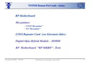
TOTEM Roman Pot Cards - status. RP Motherboard Mezzanines: - “VFAT Mezzanine” - “CC Mezzanine” LVDS Repeater Card (see Giovanni slides) Digital Opto -Hybrid Module – DOHM RP Motherboard “RP MBRD” - Tests. RP Motherboard – “RPMBRD” (1).

E N D
TOTEM Roman Pot Cards - status RP Motherboard Mezzanines: - “VFAT Mezzanine” - “CC Mezzanine” LVDS Repeater Card (see Giovanni slides) Digital Opto-Hybrid Module – DOHM RP Motherboard “RP MBRD” - Tests
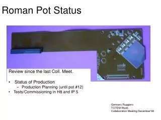
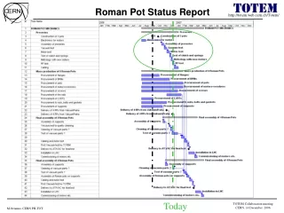
RP Motherboard – “RPMBRD” (1) Block Diagram Top Bottom - 4 cards V2 have been produced – this week expecting delivery; - Components are ready to be mounted on 1 pcs – start this week; - Full test needed before mounting the other 3 cards;
LVDS Trigger GOH 4 LVDS to CMOS LVDS with Repeaters - 32 Outputs Coincidence Chips: - 10 x 16 Trigger Outputs TR Data Out TR VFAT S (1,3,5,7,9) CC ODD REPEATERS REPEATERS S (2,4,6,8,10) CC EVEN TR Data Valid LVDS to CMOS GOH 5 Trigger VFAT: - receive 32 Trigger Outputs from LVDS to CMOS converters; - receive T1 from PLL25; - send TR Data Out to the Data Stream (via GOH3); - send TR Data Valid to GOH4 and GOH5; Optical via - GOH4 and GOH5 - Data Valid from: TR VFAT or CCU or TR VFAT S1 bit RP Motherboard – “RPMBRD” (2) Zoom on Trigger outputs
VFAT and CC mezzanines • VFAT Mezzanine: • Also Trigger VFAT (for RP Motherboard); • One VFAT chip with 32 inputs; • Standard 50pins output connector • Several PCB produced, 1 mounted , to be tested • CC Mezzanine: • One Coincidence Chip (CC); • 80 LVDS inputs; • 16 LVDS outputs; • I2C control • 3 pcs produced at CERN • Tested I2C channel only on “RPMBRD” - V1
LVDS Repeater Card • LVDS Repeater Chip: • Repeat 16 LVDS signal lines; • Chip in package: TQFP64pins; • LVDS Repeater Card: • D-SUB 37pins male/female connectors; • Placed inside plastic hood; • Schematic – done and soon the layout;
LVDS Repeater Chip – Tests (1) Differential Probe Power supply O U T P U T I N P U T Oscilloscope Signals Generator Differential Signal Single ended CHIP IDEAL SETUP • 2 differential probes • 2 chips on repeater cards and cable Chip + card Chip + card Delay measurement
LVDS Repeater Chip – Tests (2) O U T P U T I N P U T 40MHz 2MHz
TOTEM - Control System General Blocks, Characteristics • I2C for DOH outside; • few channels on LEMO; • close to DOHM • Fault repair reconfiguration example • bypass CCUM-3 Secondary DOHM B1 B2 DOH 2 B CCUM-4 CCUM-3 CCUM-N CCUM-2 CCUM-1 B1 B2 B1 B2 CCU FEC X I2C 1 A DOH 1 I2C 2 Up to 16 I2C channels each DOH controlI2C out Primary DOHM * • Two Digital Opto-Hybrids modules; • Communication and Control Unit (CCU), LVDS buffers • and multiplexer; • A and B channels: • optical from/to FEC; • electrical on the INPUT and OUTPUT connectors; • DOH I2C control from outside; • * Based on TOB DOHM from CMS
DOHM - status • 25 PCB produced; • 2 mounted with DOH mezzanines - used at CERN; • - DOH mezzanines are with 2m fiber – need to be cut and spliced! • - Possible, tools exist, but it is extremely delicate procedure (expert technician CMS) • Components and cable to order for remaining
CCUM Carrier B2 B2 B1 B1 A A I2C 1 I2C 2 DOH controlI2C out • Two CCUM modules; • I2C channels for DOHM and on LEMO connectors; • Can be divided on 2 independent boards – losing half of the I2C channels and second I2C • channel from next CCUM; • Schematic, Layout, Components order - stillpending • “CCUM Carrier” – is needed due to the DOH redundancy requirements and also due to the • requested I2C channels for T2 !!!
Control/Readout Crate CAEN TOTFED FEC TTCci RP Motherboard - “RPMBRD” – tests (1) • System in 555 for testing RPMBRD: • - Hardware: • - PC (CAEN VME controller) + VME Crate; • - TTCci + FEC + DOHM + RPMB – for control part; • - RPMB + TOTFED + S-Link64 or VME or USB – for readout and trigger part Control Fibers Data Fibers S-Link64 RPMBRD 10 RP Hybrids PC DOHM
RP Motherboard - “RPMBRD” – tests (1) - Software: - Control: - I2C access to all devices: - 10 RP Hybrids (4 VFAT + DCU each); - 2 CC mezzanines; - 1 VFAT Trigger Mezzanine; - 1 PLL25; - 5 GOH modules; - 1 CCUM module - T1 commands to VFAT; - TTCci + FEC sends command/clock to RPMB; - Synch from TTCci; - Run VFAT Hybrid tests - Readout and optical Trigger (electrical Trigger after CC mezzanine); - GOHs + TOTFED – via VME or USB; - Synch from TTCci - DCS information (Temperature, RADMON, Pressure sensors)
Conclusions RP Motherboard: - V2 produced - Final Tests - in progress; - Final Production, Order of Components and Tests – pending; Mezzanines: - “VFAT Mezzanine” – prototype produced, to be tested; - “CC Mezzanine” – prototype produced, to be fully tested; LVDS Repeater – layout pending DOHM – ready for production