Download
1 / 1
20 likes | 161 Views
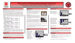
The Effect of Electrical Stimulation on in vitro Diabetic Ulcer Models Team ELECTRODE: Evaluating Linear-Radial Electrode Conformations for Tissue Repair and Organizing a Device for Experimentation

E N D
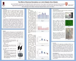
The Effect of Electrical Stimulation on in vitro Diabetic Ulcer Models Team ELECTRODE: Evaluating Linear-Radial Electrode Conformations for Tissue Repair and Organizing a Device for Experimentation Sagah Ahmed, Natalie Anzures, Zach Bosley, Brendan Bui, ArianaFeizi, SudiJawahery, Courtney Koenig, Katie Lakomy, Megan Lin, PoornaNatarajan, Eisha Nathan, HibaSayed, Eduardo Solano, and Dr. John Fisher Figure 9. • Results Introduction Chronic diabetic ulcers are a pressing medical concern that affects approximately 15% of patients with diabetes worldwide. Complications related to ulcers frequently result in lower-limb amputations and are the leading cause of diabetes-linked hospitalizations. Current treatments for diabetic ulcers include invasive surgery, therapeutic footwear, and hyperbaric oxygen treatment. However, these treatments have major limitations due to their adverse side effects, need for constant application, and low reliability. The application of a low-voltage electrical stimulus across tissue layers has been shown to trigger wound-healing pathways. The lack of angiogenesis (vascular tissue formation) in chronic diabetic ulcers is a major cause of infection and slow healing rates. Our objective is to demonstrate the effect that linear (constant) and radial (non-constant) electric fields have on angiogenic wound healing pathways. We will measure the effects of both electrical fields on cell migration, cell proliferation, VEGF expression, and bFGF expression. We hypothesize that the application of an electrical stimulus to the wound will help alleviate the inflammatory tissue response, increase levels of angiogenesis, and reduce the healing time of diabetic ulcers. Experimental Setup The experiment is divided into stages of stimulation, cell proliferation analysis, and cell migration analysis: Figure 8. Cell Proliferation Cell proliferation was determined by obtaining Live/Dead images to assess cell viability and density for the experimental groups and control at 24h and 48h post stimulation. Cell density was normalized to the initial seeding density at -72h. Statistics were analyzed relative to the control values at each time point and voltage. At 0.01V, there was a significant increase in cell density at 48h (n=9, p<0.05). At 0.1V, cell density significantly increased at 24h (n=9, p<0.05). Figure 4 shows that the voltages applied do not induce significant cell death across all the groups. Figure 5 is a magnified view of the low density of dead cells from Figure 4. * * * Figure 8 shows the experimental setup of the linearly applied electric field. The three wells on the left are the controls, meaning no electrical stimulation is applied. The three wells on the right are the experimental wells, meaning either a voltage of 0.01V, 0.1V, or 1V is applied. Figure 4. Figure 9 depicts an example of measuring cell proliferation. A sample is taken from each control and experimental well and cells are fluorescently stained. Live cells are visualized as green due to green fluorescent-Calcein staining the cell membrane. Dead cells are visualized as red due to Ethidiumhomodimer III staining the disrupted membrane areas. Live/dead samples are examined under a fluorescent microscope and cells are counted using ‘Image J’ software. * * Figure 5. • Methods • Electrical stimulation is tested using an in vitro model of RAOECs (rat aortic endothelial cells). Endothelial cells are directly affected in the wound healing process, and an in vitro model of RAOECs allows for measurement of growth factor expressions. RAOECs are plated in four 6-well-plates at a seeding density of 150,000/9.5 cells/cm2. Prior to electrical stimulation, cells are scraped to simulate an open wound such that only a 1-cm radial or linear strip of confluent RAOECs remains. This 1-cm strip is then subjected to DC (direct current) electrical stimulation. Figure 10 is an example of how cell migration in the direction of the arrow was measured. Three images under 2.5X magnification are taken along each side of the line of cells. At 0h, 4.5h, and 9h, migration distances are measured from their starting point to the edge of the stimulated cell population. • Cell Migration • Figure 6shows migration data for an averaged control and experimental stimuli at 0.01V, 0.1V, and 1V. A one-way analysis of variance test (ANOVA) was performed to determine the statistical differences between various electrical stimulation groups over time. At 4.5h, cells stimulated at 0.01V and 0.1V migrated a significantly greater distance (n=90, p<0.05) in the direction of the electrical field compared to the control. At 9h, cells stimulated at 1V migrated a significantly greater distance (n=90, p<0.05) against the electric field compared to the control. Migration of cells at 4.5h compared to that of 9h stimulated at 0.01V and 1V was statistically different. Figure 7 shows the migration rates. * * Figure 6. • Figure 1 is a graph of the electrical stimulus with the following parameters applied to all experimental wells for 30 min: • 0.01V, 0.1V or 1V • 50 Hz • 50% duty cycle • Figure 2 shows the electric field for the linear device while Figure 3 shows the electric field for the radial device. • The following data collection steps are performed: • Images are taken of cell strip location 0h, 4.5h and 9h post stimulation for cell migration data • Live/dead pictures are taken 24h and 48h after stimulation for cell density data and to assess cell viability • Future work will include analyzing VEGF (vascular endothelial growth factor)andbFGF expression (basic fibroblast growth factor) using qRT-PCR Voltage Figure 10. • Conclusion • The objectives of this study were to investigate the effects of an optimized linearly and radially applied electrical field (in vitro) on cell proliferation, cell migration, VEGF expression, and bFGF expression. Results show that application of an electric field increases cell migration. Cell proliferation tests show successful cell cultures with the amount of dead cells being negligible. Thus, this study shows that applying a linear electric field onto in vitro rat aortic endothelial cells induces and improves the natural healing process. Future work includes testing the effectiveness of a radially applied electric field (in vitro) and either a linearly or radially applied electric field (in vivo). • Acknowledgements • We would like to thank Dr. Dagenais, (Dept. of Electrical & Computer Engineering); K. Ferlin, B. Nguyen, M. Wang, T. Zhu (lab graduate students); and Dr. Coale, Dr. Skendall, Dr. Creek, Dr. Wallace, Dr. Thomas (Gemstone directors and staff). Our research is supported by an Undergraduate Research Fellowship from the Howard Hughes Medical Institute. Time * Figure 1. * Figure 7. * Figure 2. * Figure 3.