Download
1 / 27
270 likes | 470 Views
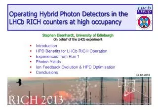
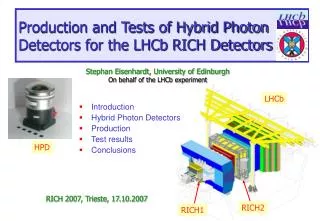
Production and Tests of Hybrid Photon Detectors for the LHCb RICH Detectors. Stephan Eisenhardt, University of Edinburgh On behalf of the LHCb experiment. Introduction Hybrid Photon Detectors Production Test results Conclusions. LHCb. HPD. RICH 2007, Trieste, 17.10.2007. RICH2. RICH1.

E N D
Production and Tests of Hybrid Photon Detectors for the LHCb RICH Detectors Stephan Eisenhardt, University of Edinburgh On behalf of the LHCb experiment Introduction Hybrid Photon Detectors Production Test results Conclusions LHCb HPD RICH 2007, Trieste, 17.10.2007 RICH2 RICH1
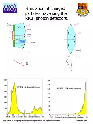
RICH1 RICH2 C4F10(small) Aerogel(large) CF4 RICH Photondetector Requirements single event full LHCb simulation used in performance studies photodetector area: 3.3 m2 single photon sensitivity: 200 - 600 nm quantum efficiency: >20% good granularity: 2.5 x 2.5 mm2 active area fraction: 65% # of electronic channels: 500k LHCb DAQ rate: 40MHz rad. tolerant: 3kRad/year answer: 484 Hybrid Photon Detectors Stephan Eisenhardt
Hybrid Photon Detector (HPD) • Photon detector: • Quartz window, S20 photocathode • Typical QE dE > 0.7eV • Cross-focussing optics (tetrode structure): • De-magnification by ~5 • Active diameter 75mm 484 tubes for overall RICH system • 20 kV operating voltage (~5000 e– [eq. Si]) • Anode: • 25632 pixel Si-sensor array (“Alice mode”) small pixels low noise • bump-bonded to binary readout chip • assembly encapsulated in vacuum tube • “LHCb readout mode”: 8-fold binary OR effective 3232 pixel array • pixel size 500mm500mm sufficient Anode Vacuum photon detector Stephan Eisenhardt
20 m Detector chip (Canberra) Assembly probing High T bump-bonding (VTT) Readout chip (IBM) Wafer probing Packaging (HCM) Anode testing Visual inspection and plating control Ceramic carrier (Kyocera) Brazing (DEP) and gold-plating (CERN) HPD manufacture – Anode challenge: • 7 companies/institutes • 6 countries • coordinated by LHCb tests by LHCb Stephan Eisenhardt
HPD manufacture – Tube (@DEP) HPD tube production (DEP) Vacuum bake-out@ 300°C Photo-cathode deposition and vacuum sealing HPD cabling and potting Tube body assembly Final HPD testing by LHCb Anode incoming inspection and testing Anode testing QE measurement and anode testing Stephan Eisenhardt
Dark box HPD flat & pointing light source Electronics & Power supplies DAQ PC Photon Detector Test Facilities • Photon Detector Test Facilities (PDTF): (Edinburgh & Glasgow) • 2 test stations per site • design test rate: 1 HPD / day / site • standard preparation and automated test programme per HPD: ~6hrs • extended tests: on ~10% of HPDs • Quantum Efficiency (Edinburgh) • Backpulse Signal (Glasgow) • HPD Storage: • under He-free atmosphere: N2 gas flow (0.2 l/min) PDTF station Stephan Eisenhardt
PDTF – Tests • Comprehensive test of every function and parameter of the HPD: Electron Optics / Tube Volume Imaging Demagnification HV Stability Field Distortions Ion Feed Back Vacuum Quality Photocathode Dark Count Response to light Quantum Efficiency HPD Body Dimensions Quartz window Pin Grid Array Sensor position Readout Chip Connections Communications DAC linearity Readout modes Dead Channels Noisy Channels Pixel masking Threshold Noise Silicon Sensor IV Curve Depletion Bump-Bonding Efficiency (Backpulse) Stephan Eisenhardt
Bias Voltage Scan HV Scan Strobe Scan HV ramp up PDTF Taskflow Temp monitor Threshold Scan Dark Count – Alice mode LED light – Alice mode LED monitor HV monitor Bias V monitor Initialisation Dark Count - LHCb mode IV Scan LED light - LHCb mode Power ON PDTF – Automation of Tests automation: • parameter setting • data taking • logging • data analysis • report generation human control: • parameter choice • online displays • offline reports Stephan Eisenhardt
Testing Programme – Summary result: pass: 547 ~98% fail: 12 ~ 2% Stephan Eisenhardt
Mechanical Tests • 555 HPD passed • 2 HPD failed on first test • leaned by ~0.4mm tubes repaired to pass as well • t point of first possible contact PDTF: mechanical test jig HPD : 83.0mm +0.0mm -0.1mm Teflon tape: 0.1mm Jig : 83.4mm gap: 0.1mm any contact = failure Stephan Eisenhardt
Pixel Chip – Threshold and Noise • excellent signal over noise: specification <measured> • average signal charge @ 20kV: C = 5000 e- • average threshold: T = < 2000 e- 1065 e- • average electronic noise: N = < 250 e- 145 e- • signal over noise: S/N = (C-T)/N > 12 27 (min, max) = (21,33) <noise>: 145 e- <threshold>: 1065 e- <S/N>: 27 Stephan Eisenhardt
Anode – Channel Yields • development of Flip-Chip bump-bonding for O(104) channels: • excellent yields for response of individual pixels: • in “Alice mode” 8192 pixels / HPD • spec: > 95% working (< 400 pixels dead) • all HPD within spec • noisy pixels: negligible dead pixels / HPD 20 m noisy pixels / HPD Alice mode: fine resolution Stephan Eisenhardt
Anode – Leakage Current Leakage Current @ 80V bias • goal: typical value of: LC ~ 1mA • achieved for all bare chips when unpowered • in powered HPD: 1W heat dissipation • anode heat up by ~12-15 °C • increase in leakage current: ~*2 for 6 °C # HPD IV scans for sample of HPDs Leakage Current [nA] • found two classes: • low current @ 80V (<1mA): quadratic behaviour up to 90V bias • medium current @ 80V (~1mA…3mA): turn up point between: 40…60V Bias Current [nA] Bias Voltage [V] Stephan Eisenhardt
Imaging pulsed LED run (200k events, ~3 npe/event) fit for sensor position displacement in y [mm] cylindrical reflection: reflection on Al coating circles: LHCb pixel Ø displacement in x [mm] fit for image diameter sensor displacement: due to positioning error >1mm (2 LHCb pixel): signal loss possible in magnetic field # HPD linear demagnification: <D> = 5.45 Stephan Eisenhardt linear demagnification
Photoelectron Response • HV scan: look for photon yield • onset of response • onset of charge sharing between pixels • slope due to increasing efficiency for back-scattered e- (only partial energy deposit) • all accepted HPD pass pixel hit rate cluster hit rate photoelectrons / event HV [kV] Stephan Eisenhardt
Anode Response – Bias Voltage Scan • Bias voltage scan: look for photon yield • onset of response • bias of full depletion • plateau of over-depletion >50V • all accepted HPD pass pixel hit rate cluster hit rate photoelectrons / event working point Anode Bias [V] Stephan Eisenhardt
Dark Count Response • Dark Count settling after first HV ramp up: • observation of signals without light source • typical decay: factor 2 in 30min after initial ramp-up • time constants vary • all accepted HPD pass pixel hit rate dark counts / event cluster hit rate Time [min] Stephan Eisenhardt
H516018: 10.0 kHz/cm2 H516009: 7.3 kHz/cm2 high red sensitivity increased IFB prob. Dark Count • all accepted HPD have a very low dark count < 20kHz/cm2 • DC = 5 kHz/cm2 : 1% probability for 1 hit / HPD / event • 497 HPD with DC < 5 kHz/cm2 settled Dark Count from high statistics run • in the range 5…20 kHz/cm2: • two types: • high red sensitivity • increased IFB probability • perfectly fine to be used in RICH # HPD Dark Count [kHz/cm2] Stephan Eisenhardt
Ion Feed Back • due to e- ionising residual gas atoms ion produces bunch of photoelectrons at photocathode cluster of hits with 200-300ns delay • we find: very low IFB very good tube vacuum at fabrication HPD response to 15ns LED pulses with varied delay Ion Feed Back from delayed cluster signals <IFB> = 0.04% spec: max. 1% Very low IFB <<1% hits / event # HPD Delay [ns] 50ns strobe signal Ion Feed Back [%] Stephan Eisenhardt
Quantum Efficiency – DEP Data <QE> (DEP Data): across delivery batches • Excellent sensitivity: • increase due to process tuning at DEP • single most helpful improvement to RICH performance • <QE @ 270nm> = 30.8% >> typical QE = 23.3% <QE> per delivery batch QE [%] RMS of batch spread QE [%] Wavelength [nm] • more tuning improvements: • fill of sensitivity dip between UV and visible • reduction of red sensitivity @ 800nm • anti-correlated to blue sensitivity • cause of thermal e--emission (dark count) Batch number Stephan Eisenhardt
QE – LHCb Verification • PDTF measurement: • 7 wavelengths, 10nm bandpass filter • error: 2% • 76 HPD measured • PDTF QE measurements typically matches DEP values within 3% 4 tests across QE range QE all tests: PDTF vs. DEP wavelength [nm] • PDTF measurements confirm shape of spectra & absolute values • full trust in DEP measurements QE – PDTF Stephan Eisenhardt QE – DEP
Conclusions • Production & testing of >550 HPDs has finished • Rigorous test programme with: ~98% of HPDs accepted pass: 547 HPD fail: 12 HPD • HPDs meet requirements of LHCb RICH detectors • Very good results for vacuum quality and Dark Count • Excellent results on Quantum Efficiency and S/N • DEP Quantum Efficiency results confirmed by PDTF • Commissioning is underway with 288 HPD installed in RICH2 Stephan Eisenhardt
Backup Slides Stephan Eisenhardt
Classification System • guideline for usability in RICH: • 161x class A+: exceed specifications significantly • 282x class A: clear pass in all aspects • 60x class B : may fail specs, but recommended for usage • HPDs with slightly increased dark count • 42x class E: flagged with an issue, still usable in RICH • HPDs with increased LC or 1…5% dead pixels • 12x class F : clear fail reject • 12 failed HPDs: • 9x replaced with good HPD • 3x accepted as failure within LHCb responsibility • misc: • 4x repaired, retested and accepted as good • 2x anode problem, but usable, under study, not classified pass: 545+2 of 559 ~ 98% fail: 12 of 559 ~ 2% Stephan Eisenhardt
Filter System Reference Photodiode Quartz-Tungsten Halogen Lamp Dark Box HPD photocurrent: <160nA image Ø: ~ 50mm Fused Silica Lens Interlock Shutter , 10nm BP filter , IR or VIS block , ND filter RL IHPD [pA] IPD [pA] Bias[V] QE – PDTF Test Setup • measurement of the photocurrent, referenced with calibrated photodiode • differing DEP parameters: • Bias: 900V • Ø: 10-15mm • large photo currents default: 100V cross-check: 22V (just below He ionisation threshold) Stephan Eisenhardt
QE – Effect of degrading Vacuum • degraded vacuum causes: • increase of Ion Feed Back • increase of charge per photoelectron • increase of measured photo current • fake increase in determined QE • cure: • measure photo current below He ionisation threshold • PDTF : IV curves 0…500V • PDTF : bias = 100V, 22V • DEP : bias = 900V case of extreme vacuum degradation for good illustration 22V Stephan Eisenhardt
Photoelectron Efficiency – Backpulse • comparison of binary to analog event yield with constant light source • binary: through readout chip npe • analog: measurement of the charge pulse on the bias line Poisson <m> capacity of whole chip: noise*104 wrt. single pixel • Poisson fit to analog spectrum • Results: efficiency = npe / <m> strobe length efficiency 25ns 50ns PDTF 2007 88% 94% (production HPDs) CERN 2004 84% 92% (prototype HPDs) error estimation pending analog ph.el. spectrum photo electrons data fit events an almost perfect match 2 3 4 1 fit yields Poisson <m> 5 pedestal subtracted ADC counts Stephan Eisenhardt