WFIRST Coronagraph Instrument Reference Information
230 likes | 251 Views
The WFIRST Coronagraph Instrument (CGI) is a technology demonstrator for directly imaging Earth-like exoplanets. This information provides details about the instrument's design, architecture, and predicted performance. The CGI showcases the technologies needed to image and characterize rocky planets in the habitable zones of nearby stars, reducing the cost and risk of future missions.

WFIRST Coronagraph Instrument Reference Information
E N D
Presentation Transcript
WFIRST Coronagraph InstrumentReference Information February XX, 2018 Information here pertains to the design being developed during Phase A for the Mission System Requirements Review
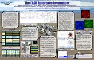
Coronagraph Instrument (CGI) The Coronagraph Instrument on WFIRST is an advanced technology demonstrator for future missions aiming to directly image Earth-like exoplanets. Post- Processing High-contrast Integral Field Spectroscopy Ultra-low noise photon counting Visible Detectors High-contrast Coronagraph Masks Ultra-stable Space Telescope & Observatory Autonomous Ultra-Precise Wavefront Sensing & Control Large-format Deformable Mirrors • CGI will premiere in space the technologies needed to image and characterize rocky planets in the habitable zones of nearby stars. By demonstrating these tools in a system with end-to-end, scientific observing operations, NASA will reduce the cost and risk of a potential future flagship mission. Coronagraph Instrument Reference Information
Required & Predicted CGI Performance in the Context of Existing Capabilities Coronagraph Instrument Reference Information
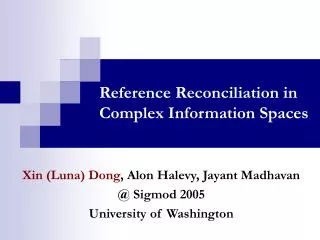
CGI Architecture High Order Wavefront Sensing/ Control Filter wheel Field stop mask SPC mask Focal plane mask Lyot mask Light From Telescope Fast Steering Mechanism Hybrid Lyot Coronagraph Shaped Pupil Coronagraph Deformable Mirror 1 OAP2 IFS/Img Selector OAP4 OAP1 DICAM Focus Correction Mechanism Radiation Shield Mirror Off Axis Parabola 8 Fold Mirror OAP3 OAP7 OAP5 OAP6 Deformable Mirror 2 LOCAM IFC Low Order Wavefront Sensing/ Control 5 mHz 5 mHz 1 kHz Integral Field Spectro-graph IFSCAM • Direct Imaging Camera • Integral Field Spectrograph (R = 50) • Photon-Counting EMCCD detectors • 2 Coronagraph mask technologies (HLC, SPC) • 2 Deformable Mirrors • Low-Order Wavefront Sensing & Control WFC Coronagraph Instrument Reference Information
CGI Architecture CGI optical bench FSM DM 2 DM 1 DM electronics Structural frame • The first deformable mirror, DM 1, is positioned at a relay pupil following the FSM. DM 2 is positioned 1 meter away to enable correction of amplitude errors and phase errors originating from out-of-pupil surfaces. • Both coronagraph mask types, the Hybrid Lyot and Shaped Pupil Coronagraphs (HLC and SPC), are implemented on the same optical beam train and selected by changing masks at the planes labeled Pupil Mask Fold, Focal plane mask, and Lyot Stop. • The filter and the camera channel (either the Direct Imaging Camera or the Integral Field Spectrograph) are selected by mechanisms after the Lyot stop. IFC • In the WFIRST Payload, CGI mounts onto the Instrument Carrier (IC) shared with the Wide Field Instrument. The Tertiary Collimator Assembly (TCA; not shown) is the optical interface between the telescope and CGI, and relays an exit pupil onto the Fast Steering Mirror (FSM). WFC Coronagraph Instrument Reference Information
Baseline Masks and Filters DI Field stop mask changer Occulting mask changer (magnified for illustration) Lyot mask changer Camera selector Pupil mask changer Filter wheel IC Un-pol Imaging Lenses 10% BW 1 1 1 Hybrid Lyot HL HL HL Plain mirror 0-pol HL 10% BW 4 4 4 IFS 45-pol 4 Disk 90-pol 18% BW Shaped Pupil c SP SP 2 SP 2 Open c c c Char. 135-pol 3 3 18% BW Mirror Star- Shade Comp. Starshade filters (per ICD) Dichroics for starshade (per ICD) 1a,1b, 1c x5 3% BW x3 x3 4a,4b, 4c 3% BW Pupil Lens x3 Pinhole ND4 filter Engr. Phase Retrieval #1,2,3, 4 1% BW IFS x4 Open Open Dark mask Open Open • 1=575 nm, 10% (annular, 3-9λ/D)2=660 nm, 18% (bow-tie / IFS, 3-9 λ/D) • 3=760 nm, 18% (bow-tie / IFS, 3-9 λ/D)4=825 nm, 10% (annular, 3-19 λ/D)
Baseline Filters Log10(κ) 4 2 3 1 Full Disk Albedo Wavelength (nm) Karkoschka (1994) Hα • 1=575 nm, 10% (annular, 3-9λ/D)2=660 nm, 18% (bow-tie / IFS, 3-9 λ/D) • 3=760 nm, 18% (bow-tie / IFS, 3-9 λ/D)4=825 nm, 10% (annular, 3-19 λ/D)
Baseline Observing Modes Coronagraph Instrument Reference Information 8
CGI Filter Table Additional instrument parameter tables at https://wfirst.ipac.caltech.edu/sims/Param_db.html Coronagraph Instrument Reference Information
Starshade Compatibility Starshade filters • The WFIRST baseline design is starshade-ready, to support exoplanet observations with an external starshadeocculter in the event that one is launched in the future. • CGI has 3 starshade-dedicated dichroic Zernike sensor masks in the occulter wheel to enable closed-loop lateral sensing using the LOWFS camera. • CGI has 5 dedicated filters for scientific observations with a starshade, suitable for both the direct imaging and IFS cameras. These filters accommodate observations with a potential future starshade probe mission. They are held in the CGI Field Stop changer (column 4 of the mask-filter schematic in slide 6). Starshade probe concept study reports available at https://exoplanets.nasa.gov/exep/studies/probe-scale-stdt/ Coronagraph Instrument Reference Information
Hybrid Lyot Coronagraph • The HLC design incorporates a numerically optimized, static actuator pattern applied to both deformable mirrors. • Occulting mask is a r = 2.8 λc/D partially-transmissive nickel disc overlaid with a radially-and-azimuthally varying dielectric coating. • Lyot stop is an annular mask that blocks the telescope pupil edges and struts. • 2017 design PSF core throughput is 4.5% relative to the energy incident on primary mirror (ignoring losses from reflections and filters). Simulated HLC PSF including aberrations and high-order wavefront control operations, illustrating the annular dark zone between 3 and 9 λc/D. Each sub-panel represents a different scenario for DM probe wavelength resolution and detector sampling. • References • J. Trauger, D. Moody, et al., JATIS Vol 2, id. 011013 (2016) - https://doi.org/10.1117/1.JATIS.2.1.011013 • J. Krist, et al., Proc SPIE Vol 10400, id. 1040004. (2017) - http://dx.doi.org/10.1117/12.2274792 • K. Balasubramanian, et al., Proc SPIE Vol 10400, id. (2017) - https://doi.org/10.1117/12.2274059 HLC Lyot stop. Diagram of Lyot stop model: white represents the transmitted region; black represents the telescope pupil; gray represents the region blocked by the stop in addition to the telescope pupil. HLC occulting mask. Surface height measurement of an occulting mask fabricated by the JPL Micro Devices Lab. Recent design iterations like the one shown here utilize an azimuthally varying dielectric profile. Coronagraph Instrument Reference Information
Shaped Pupil Coronagraph • The shaped pupil apodizer is a reflective mask on a black Silicon substrate. • The occulting mask is a hard-edged diaphragm with either a bowtie-shaped or annular aperture, depending on whether the characterization (spectroscopy) or debris disk shaped pupil is selected. • The Characterization SPC designed in 2017 produces a 2 x 65° bowtie dark zone from 3 – 9 λc/D over an 18% bandpass, and has a PSF core throughput of 4.3% relative to the energy incident on primary mirror (ignoring losses from reflections and filters). • The Debris Disk SPC design produces a 360° dark zone from 6.5 – 20 λc/D in a 10% bandpass. Characterization SPC simulations at λc = 660 and 770 nm including system aberrations, pointing jitter, and wavefront control operations. The circles correspond to r = 3 and 9 λ c /D. • References • N. T. Zimmerman, et al., JATIS Vol 2 id. 011012 (2016) - http://dx.doi.org/10.1117/1.JATIS.2.1.011012 • K. Balasubramanian, et al., JATIS Vol2 id. 011005 (2015) - https://doi.org/10.1117/1.JATIS.2.1.011005 • A. J. E. Riggs et al., N. T. Zimmerman, et al., Proc SPIE Vol 104000O (2017) - http://dx.doi.org/10.1117/12.2274437 • J. Krist, et al., Proc SPIE Vol 10400, id. 1040004. (2017) - http://dx.doi.org/10.1117/12.2274792 Characterization shaped pupil coronagraph masks. 2017 design by A. J. E. Riggs. Coronagraph Instrument Reference Information
Wavefront Control • The baseline CGI design includes 4 active optics to control the wavefront: a fast steering mirror (FSM), a flat focusing mirror (FocM), and two deformable mirrors (DM 1 and DM 2) with 48x48 actuators each. • High-order wavefront control is implemented by the Electric Field Conjugation (EFC) method. The EFC loop operates on science focal plane data by measuring the interaction of aberrated on-axis starlight with a sequence of DM actuator probes. • Pointing, focus, and low-order wavefront drifts are sensed by the Low-Order Wavefront Sensing and Control (LOWFS/C) subsystem using the Zernike phase-contrast technique on starlight rejected from the occulting mask. Corrections to Zernike modes Z5—Z11 are applied to DM 1 with an update interval on the order of 100 sec. • The FSM control loop operates at 1 kHz to correct line-of-sight pointing jitter to below 1 milliarcsec. Conceptual diagram of the Zernike phase contrast wavefront sensor (F. Shi, et al., 2016). Optimized DM surfaces applied in HLC data simulations. • References • T. Groff, A. J. E. Riggs, et al., JATIS Vol 2, id 011009 (2015) - https://doi.org/10.1117/1.JATIS.2.1.011009 • F. Shi, et al., JATIS Vol 2, id 011021 (2016) - https://doi.org/10.1117/1.JATIS.2.1.011021 • J. Krist, et al., JATIS Vol 2, id 011003 (2015) - https://doi.org/10.1117/1.JATIS.2.1.011003 Coronagraph Instrument Reference Information
Integral Field Spectrograph • Lenslet-based integral field spectrograph (IFS) with R=50 spectral resolving power and a 1.6-arcsec field of view. • A reflective relay feeds a lenslet array, which critically samples the coronagraph image (2 lenslets per λc/D at 660 nm). The light from each spatial element is dispersed by a prism group. • The prioritized spectroscopy demonstration filter is an 18% bandpass centered at 760 nm (CGI Science Band 3) matched to the characterization SPC. However, by design the IFS can capture an instantaneous bandpass up to 20% anywhere in the range 600 to 1000 nm. Baseline opto-mechanical layout of the CGI IFS, showing the beam progression through the relay mirrors, lenslet array, collimator, prism, and reimaging optics. The spectra are focused on a dedicated EMCCD detector (the IFScam; not shown). The IFS produces a spectrally dispersed map of the CGI focal plane, comprised of a grid of interleaved microspectra. There is one microspectrum for each lenslet, or spatial element (center). A wavelength-resolved data cube (right hand side) is reconstructed by software. • References • M. McElwain, A. Mandell, Q. Gong, et al., Proc SPIE Vol 9904 (2016) • M. Rizzo, T. Groff, N. Zimmerman, et al., Proc SPIE Vol 10400 (2017) • A. Mandell, T. Groff, Q. Gong, et al., Proc SPIE Vol. 10400 (2017) Coronagraph Instrument Reference Information
EMCCD Detectors • Electron Multiplying CCDs are advantageous for observing very low flux sources like directly imaged exoplanets. They rely on avalanche multiplication of collected charge to greatly reduce read noise as compared to conventional CCDs. EMCCD detectors are baselined for both the Direct Imaging and IFS cameras on CGI. • A Pre-Phase-A technology development effort led by JPL accelerated the maturity of e2v’s CCD201-20 EMCCD for space flight. This included radiation environment testing, performance optimization, and thermal environment testing. • CGI exposure time calculations incorporate models of charge traps and transfer inefficiency cause by radiation displacement damage. • JPL’s EMCCD test lab has measured sensitivity thresholds before and after a radiation displacement damage dose (DDD): • Beginning of life: 0.002 e-/pixel/frame for 3×3 pixel PSF, equivalent to detection of a 35th mag star using WFIRST telescope without the coronagraph.After > 6 years radiation damage at L2: 0.007 e-/pixel/frame for 3×3 pixel PSF e2v CCD201-20 Image section Store section CGI will operate its EMCCDs in photon counting mode. By thresholding the readout charge values to register each pixel as either 0 or 1 photoelectrons, the 1.4x excess noise factor that originates in the uncertainty of the avalanche multiplication gain is eliminated. • References • L. Harding, R. Demers, et al., JATIS Vol 2, id 011007 (2016) Coronagraph Instrument Reference Information
Operations Concept Coronagraph Instrument Reference Information
Data Post-Processing 2. Post-processing trials on Laboratory Data • Investigations on algorithms for CGI data post-processing have encompassed both end-to-end data simulations and analysis of laboratory testbed data. • Reference differential imaging (RDI) trials have probed a range of wavefront stability and noise scenarios. Simulations with spacecraft rolls have also enabled tests of Angular differential imaging (ADI). 1. Post-processing trials on HLC data simulations The enhancement provided by PCA-based algorithms like KLIP depends on the level of correlation between the speckle patterns in the science image and the reference library. Raw, roll 2 Raw, roll 1 Raw, ref. • References • M. Ygouf, N. Zimmerman, L. Pueyo, R. Soummer, et al., Proc. SPIE Vol 9904 (2016) - http://dx.doi.org/10.1117/12.2231581 • M. Ygouf, et al., WFIRST-STScI-TR1605 (2016) - http://www.stsci.edu/wfirst/technicalreports/WFIRST-STScI-TR1605.pdf • M. Ygouf, et al., WFIRST-STScI-TR1601 (2016) - http://www.stsci.edu/wfirst/technicalreports/WFIRST-STScI-TR1605.pdf Recovered point source Example application of RDI to SPC data from the OMC testbed, demonstrating the match-filtered recovery of a fake point source inserted into one image. Coronagraph Instrument Reference Information
Community Data Challenges • The WFIRST Exoplanet Data Challenges are a series of blind spectral retrieval exercises based on simulated CGI data, designed to inform instrument engineering trades and operations concepts. • Participation in the Data Challenges is open to the community of exoplanet atmosphere modelers. IPAC hosts a WFIRST Data Challenges website with information on how to register: https://wfirst.ipac.caltech.edu/sims/CGI_Data_Challenges.html Simulated spectra for three of the four exoplanets at the highest signal-to-noise and resolving power (top row) and at the lowest signal-to-noise and resolving power (bottom row). Coronagraph Instrument Reference Information
Pre-Phase A Technology Milestones and Reports Coronagraph Instrument Reference Information
Phase A Technology Milestones Coronagraph Instrument Reference Information
Laboratory Demonstrations Results from the Occulting Mask Coronagraph (OMC) Testbed at JPL HCIT HLC SPC Dynamic contrast demonstration with a Low Order Wavefront Sensing and Control (LOWFS/C) system integrated on the Occulting Mask Coronagraph testbed. When line-of-sight disturbances are introduced on the testbed, the LOWFS senses the pointing error and corrects it by commanding a fast steering mirror. Demonstrations with both the SPC and HLC masks surpassed their 1E-8 contrast goal (F. Shi, et al., Proc SPIE Vol 10400, 2017). Normalized intensity maps measured on the OMC testbed in broadband (10 %) light. • References • F. Shi, E. Cady, et al., Proc. SPIE Vol 10400 (2017) - http://dx.doi.org/10.1117/12.2274887 • E. Cady, K. Balasubramanian, et al., Proc. SPIE Vol 10400 (2017) - http://dx.doi.org/10.1117/12.2272834 • B.-J. Seo, E. Cady, et al., Proc SPIE Vol 10400, 10.1117/12.2274687 (2017) - http://dx.doi.org/10.1117/12.2274687 Coronagraph Instrument Reference Information
Simulation Resources Coronagraph Instrument Reference Information
Reference documents Coronagraph Instrument Reference Information