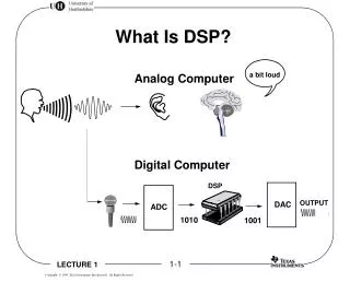
What Is DSP?
What Is DSP?. a bit loud. Analog Computer. Digital Computer. DSP. OUTPUT. DAC. ADC. 1010. 1001. A Typical DSP System. MEMORY. DSP Chip Memory Converters (Optional) Analog to Digital Digital to Analog Communication Ports Serial Parallel. ADC. DSP. DAC. PORTS. 0001. 0010. +.

What Is DSP?
E N D
Presentation Transcript
What Is DSP? a bit loud Analog Computer Digital Computer DSP OUTPUT DAC ADC 1010 1001
A Typical DSP System MEMORY • DSP Chip • Memory • Converters (Optional) • Analog to Digital • Digital to Analog • Communication Ports • Serial • Parallel ADC DSP DAC PORTS
0001 0010 + 0011 3 5 . . . Multiply and Add Add Multiply 1+2 = 3 5*3 = 15 0101 0011001100110011 xxxx 8421 xxxx 0000 0011 0000 0011 Shifted and added multiple times = MAC Operation Most Common Operation in DSP A = B*C + D Typically 70 Clock Cycles With Ordinary Processors E = F*G + A Multiply, Add, and Accumulate Typically 1 Clock Cycle With Digital Signal Processors MAC Instruction
Drop in Multiplication Times TIME (ns) 600 500 400 300 200 100 5 ns 0 1971 1976 1998 YEARS
STORED PROGRAM AND DATA A = ADDRESS D = DATA STORED DATA Digital Computers von Neuman Machine A ARITHMETIC LOGIC UNIT INPUT/ OUTPUT D Harvard Architecture A A ARITHMETIC LOGIC UNIT STORED PROGRAM INPUT/ OUTPUT D D
CACHE 64 x 32 RAM 1 1K x 32 RAM 0 1K x 32 SERIAL PORT 0 TIMER 1 DMA TIMER 0 MULTIPLEXER An ExampleTMS320C31 Architecture A23-A0 7 SEPARATE BUSES ( P / D ) D31-D0 MULTIPLIER ADDER PERIPHERAL BUS (P\D) FLOATING POINT ARITHMETIC LOGIC UNIT P = PROGRAM D = DATA
TEST S/W DESIGN OK? DSP DSP Development ADD A, B 11100010010100001001 HIGH-LEVEL LANGUAGE ASSEMBLER CODE EMULATOR N Y PRODUCT Tools of the Trade
Advantages to Digital Processing Programmability Stability Repeatability Special Applications ADC PROCESS DAC Why Digital Processing?
One Hardware = Many Tasks Upgradability and Flexibility Develop New Code Upgrade Analog Solder New Component . . . . Programmability LOW-PASS FILTER SOFTWARE 1 SOFTWARE 2 SAME HARDWARE MUSIC SYNTHESIZER MOTOR CONTROL SOFTWARE N
Analog Circuits are affected by Temperature Aging Tolerance of Components Two Analog Systems using the same design and components may differ in performance 1k + 10 years = 1.1k Analog Variability
Perfect Reproducibility Nearly identical performance from unit to unit Performance not affected by tolerance No drift in performance due to temperature or aging Guaranteed accuracy Digital Repeatability A CD player always plays the same music quality
Some special functions are best implemented digitally Performance • Lossless Compression • Adaptive Filters • Linear Phase Filters f gain phase frequency frequency f1 f2
Hi-Fi Equipment Toys Videophones Modems Phone Systems 3D Graphics Image Processing And More ... Practical DSP Systems
Low cost and simplicity in some applications Attenuators/amplifiers Simple filters Wide bandwidth (GHz) Low signal levels Infinite effective sampling rate Infinite resolution in frequency No aliasing/reconstruction issues Infinite resolution in amplitude No quantitation noise Analog Advantages
Repeatability Low sensitivity to component tolerances Low sensitivity to temperature changes Low sensitivity to aging effects Nearly identical performance from unit to unit Matched circuits cost less High noise immunity In many applications DSP offers higher performance and lower cost CD players versus phonographic turntable Digital Signal Processing (DSP) Advantages
Most transducers are analog by nature Microphones, speakers, etc. Analog circuits are required to pre-process low level signals before ADC Analog filters may be required to limit the bandwidth of signals Anti-alias (before ADC) and reconstruction filters (after DAC) Analog circuits may be required to drive output transducers A power amplifier is required to enable a DAC to drive a speaker Analog’s Place in DSP
Number Systems • Represent numbers digitally • Any number can be represented as a series of 1s and 0s • Decimal 3 in binary • Decimal 26 in binary
16 Decimal 0x10 Hex 20 Decimal 0x14 Hex Binary and Hex Decimal 0,1,2,…….,9 Binary 0,1 Hex 0,1,2,……..,A,B,C,D,E,F • 4 bits of binary system is represented by a single hex digit • Decimal 26 in binary and hex
Signed Integers • Signed magnitude integers
Two’s Complement • Conversion to two’s complement notation • Two’s complement addition
Fixed-Point Notation • Conventions • Number range is between 1 and -1 • Decimal point is always in a fixed location (e.g., 0.74, 0.34, etc.) • Multiplying a fraction by a fraction always results in a fraction and will not produce an overflow (e.g., 0.99 x 0.9999 = less than 1) • Successive additions may cause overflow • Why? • Signal processing is multiplication-intensive • Fixed-point notation prevents overflow (useful with a small dynamic range) • Fixed-point notation is less expensive • How is fixed-point notation realized in a DSP? • Most fixed-point DSPs are 16 bits • The range of numbers that can be represented is 32767 to -32768 • The most common fixed-point format is Q15 Q15 Notation
Q15 Format Dynamic range in Q15 Number representations in Q15 • Rules for operations • Avoid operations with numbers larger than 1 2.0 x (0.5 x 0.45) = (0.2 x 0.5 x 0.45) x 10 = (0.5 x 0.45) + (0.5 x 0.45) • Scale numbers before the operation 0.5 in Q15 = 0.5 x 32767 =16384
Q15 Operations Addition Multiplication 2 x 0.5 x 0.45 =
Exponent (e) Decimal 0 1 127 -1 -128 Hex two’s comp. 7F 00 01 FF 80 TMS Floating-Point Format TMS single-precision floating-point format Bit No e = exponent is a signed two’s compliment 8-bit field and determines the location of the binary Q point s = sign of mantissa (s = 0 positive, s =1 negative) f = fractional part of the mantissa; an implied 1.0 is added to this fraction but is not allocated in the bit field since this value is always present Conversion equations Special case
Calculate 1.0e0 In hex 00 00 00 00 In binary 0000 0000 0000 0000 0000 0000 0000 0000 s = 0 Equation 1 applies: X = 01.f x2e 01.0 x 20 = 1.0 f = 0 e = 0 Floating-Point Numbers Calculate 1.5e01 In hex 03 70 00 00 In binary 0011 0111 0000 0000 0000 0000 0000 0000 s = 0 Equation 1 applies: X = 01.f x2e 0011 e = 3 s111 f = 0.5 + 0.25 + 0.125 = 0.875 X = 01.875 x 23 = 15.0 decimal ...
f = 0 e = 0 More on Floating Point Calculate -2.0e0 In hex 00 80 00 00 In binary 0000 0000 1000 0000 0000 0000 0000 0000 s = 1 Equation 2 applies: X = ( -2.0 + 0.f ) x 2e ( -2.0 + 0.0 ) x 20 = -2.0 Addition 1.5 + (-2.0) = 0.5 Multiplication 1.5e00 x 1.5e01 = 2.25e01 = 22.5
Dynamic Range Ranges of number systems • The dynamic range of floating-point representation is very large • Conclusion • Largest integer x (1.5 x 10 29 ) ~ = largest floating point • Largest Q15 x (1.03 x 10 34 ) ~ = largest floating point
Fixed vs. Floating Point • DSP devices are designed as floating point or fixed point • Fixed-point devices are usually 16-bits, e.g. TMS320C5x • Floating-point devices are usually 32-bits, e.g. TMS320C3x • Floating-point devices usually have a full set of fixed-point instructions • Floating point devices are easier to program • Fixed-point devices can emulate floating point in software Comparison
TMS320 Family 16-Bit Fixed Point Devices ’C1x Hard-Disk Controllers ’C2x Fax Machines ’C2xx Embedded Control ’C5x Voice Processing ’C54x Digital Cellular Phones 32-Bit Floating Point Devices ’C3x Videophones ’C4x Parallel Processing Other Devices ’C6x Advanced VLIW Processor Wireless Base Stations/Pooled Modems ’C8x Video Conferencing