Download
1 / 23
230 likes | 364 Views
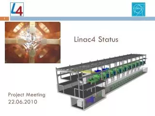
Linac4 Summary (including schedule and performance). M. Vretenar, CERN. Description, motivations Main technical issues Status Expected performance Schedule. CERN Machine Advisory Committee, 26.04.2010. Linac4 - Description. Linac4 is a new 160 MeV H ¯ linear accelerator,

E N D
Linac4 Summary(including schedule and performance) M. Vretenar, CERN Description, motivations Main technical issues Status Expected performance Schedule CERN Machine Advisory Committee, 26.04.2010
Linac4 - Description Linac4 is a new 160 MeV H¯linear accelerator, which will inject into the PS Booster (PSB). Project started in 2008, civil engineering well advanced, completion foreseen for 2015. Linac4 because 4th linac built at CERN.
Linac4 - Motivations Linac 4 is the 1st step of a programme aiming at increasing LHC Luminosity. First limitation for increased intensity from the LHC injector chain comes from space charge induced tune shift at 50 MeV injection in the PSB → need to increase injection energy! Linac2 giving serious reliability/sustainability worries: persistent vacuum problems, obsolete RF tube design → instead of an intensive consolidation program, replace with a new linac. Increase intensity for other PSB (and PS) users: ISOLDE,... Implement at CERN modern technologies for better injection and reduced losses (chopping, H- charge exchange injection). Prepare for a possible evolution towards higher intensities → Linac4 is compatible with 50 Hz operation and as injector to a high- duty cycle SPL (Superconducting Proton Linac).
Linac4 – Project History and Content 2001: proposal to build the 120 MeV warm part of the proposed Superconducting Proton Linac (SPL)in the PS South Hall, injecting H− into the PSB. 2003: energy up to 160 MeV, called “Linac4”. 2004-08: Linac4 R&D (EU program + CERN). 2007: Linac4 part of “White Paper”, approved in June Council meeting. New location under the “Mont-Citron” (no interference with running machines, extension to SPL). 2008: Official Project start. The “Linac4 Project” is composed of 3 parts: Construction and commissioning of Linac4. Construction of the transfer line, connection to Linac2 line, upgrade of the measurement lines (up to PSB wall, LBE dump). Modification of PSB injection region for H¯, 160 MeV (+ commissioning of PSB with Linac4).
Linac4 – Main Parameters • Energy of 160 MeV giving a factor 2 in bg2 with respect to Linac2 (50 MeV) space charge tune shift (limiting accumulated intensity in PSB) DQ~ N/bg2 with twice the energy, double N keeping the same tune shift. • RF frequency 352 MHz, as old LEP RF system can recuperate some klystrons and RF components from the LEP surplus. • Repetition frequency 2 Hz: 1.1 Hz present PSB limit, margin for some upgrade. • Beam current 40 mA in 400 ms: provide >2 present PSB maximum number of particles.
Linac4 Parameters H− particles + higher injection energy (160/50 MeV, factor 2 in bg2) same tune shift in PSB with twice the intensity. Ion species H− Output Energy 160 MeV Bunch Frequency 352.2 MHz Max. Rep. Rate 2 Hz Max. Beam Pulse Length 1.2 ms Max. Beam Duty Cycle 0.24 % Chopper Beam-on Factor 65 % Chopping scheme: 222 transmitted /133 empty buckets Source current 80 mA RFQ output current 70 mA Linac pulse current 40 mA N. particles per pulse 1.0 × 10¹⁴ Transverse emittance 0.4 p mm mrad Max. rep. rate for accelerating structures 50 Hz Re-use 352 MHz LEP RF components: klystrons, waveguides, circulators. Chopping at low energy to reduce beam loss at PSB. • Structures and klystrons dimensioned for 50 Hz. • Power supplies and electronics dimensioned for 2 Hz. • Infrastructure (cooling, electricity) dimensioned for 2 Hz.
Linac4 layout • Standard (normal-conducting) linac layout, based on: • pre-injector (source, magnetic LEBT, 3 MeV RFQ, chopper line) • Three different types of accelerating structures, matched to the specific energy range (max. shunt impedance, easy access and maintenance, minimum construction cost). • Beam dump at linac end, switching magnet towards transfer line – PSB. • Beam measurements at linac end and at PSB entrance. Transfer line to PSB 160 MeV 100 MeV 50 MeV Linac length ~ 80 m
Linac4 civil engineering • Main features of the “Mount Citron” site: • Length ~100m . • Simple connection with the PSB, no interference with operating machines. • Available earth shielding (place of an old spoil dump and shielding for PS) • Possible extension to the future SPL
Linac4 – RF and equipment RF: 13 LEP klystrons (1.25 MW) + 6 new klystrons (2.8 MW, pulsed) feeding 23 cavities. In the long term, pairs of LEP klystrons will be replaced by new klystrons (at end of life). Some (and eventually most) of the klystrons will feed 2 cavities.
Linac4 – Main technical challenges • Low-energy section: ion source, RFQ, chopping • Accelerating structures • PSB injection and beam optics • Linac beam dynamics • Reliability
Linac4 – Low energy 3 MeV TEST STAND in the PS Hall: • Ion source completed, first beam in July 2009, presently improving current. • Magnetic Low Energy Beam Transport • Radio Frequency Quadrupole being built at CERN, to be delivered in early 2011. • Chopping line built and tested (w/o beam). • LEP klystron (+ modulator) installed and tested in pulsed mode. • Early characterization of the low energy beam is essential for a linac project!
Linac4 – Accelerating structures Three structures of new design: DTL (Drift Tube Linac): complete revision of mechanical design w.r.t. other projects. CCDTL (Cell-Coupled DTL): new structure, first time built for a linac. PIMS (Pi-Mode Structure): new structure, first time built for a linac. DTL prototype, 2009 CCDTL prototype, 2008 R&D since 2003. Prototypes built (and tested at high RF power) for the three structures. Construction starting in 2010. PIMS prototype, 2010
PSB injection and beam optics Important modifications to the PSB injection region. The PSB is 4 superimposed rings! - Higher injection energy (new distributor). - H- charge exchange (4 rotating foil mechanisms, dumps for unstripped beam). - Some new magnets, improved instrumentation, etc. All to be installed and tested in 3 months! New working point to be determined in PSB with the Linac4 beam. Preparation of all the operational beams with the new injection Study of the high intensity beams. …all in 3 months!
Linac4 – linac beam dynamics • Beam optics design to minimize beam loss and emittance growth for: • Low activation (in particular for high duty cycle operation). • Minimum emittance growth for painting into the PSB acceptance. • Losses on concentrated spots (collimation). • LINAC4 BEAM DYNAMICS DESIGN for beam loss < 1W/m at high beam power: • Smooth phase advance transitions. • Operating point far from resonances. • Longitudinal to transverse phase advance ratio 0.5-08 (no emittance exchange). • Smooth variation of transverse and longitudinal phase advance. • Large apertures (> 7 rms beam size) 14
Linac4 - reliability • Reliability (specially in the first years!) will be a challenge for a machine that has to provide beam to all CERN. • Linac2: ~6000 hours/year with fault rate ~1.5%. • Main approach: • Prefer simple systems, with minimum number of components. • Standardized equipment (as much as possible). • Provide safety margins in the design. • Prepare failure scenarii (to be applied in case of problems). • Foresee a test period before connection to the PS Booster. • Provide a sufficient number of spares.
Linac 4 – Status April 2010 • Ion source built, improving intensity. • RFQ in construction at the CERN owrkshop. • Chopper line completed, tested without beam. • DTL prototype tested, launching orders for construction (start in June 2010). • CCDTL construction started in Russia (VNIIEF Snezinsk + BINP Novossibirsk). • PIMS prototype being completed. High power tests in June, construction will start in January 2011. • Design of dump, measurement lines and transfer line completed. • PSB equipment in construction. • RF layout defined, klystron contract placed, major orders in preparation. • RF modulator prototype1 tested, prototype2 in construction, order in preparation. • Orders for major components placed or in preparation. • Building almost completed (foreseen delivery in September 2010).
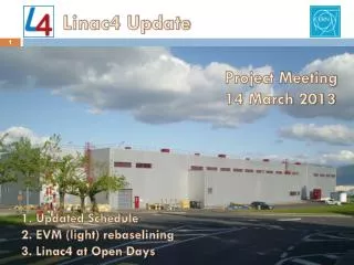
Progress in civil engineering March 2010 Oct. 2008 Start of work: 10/2008 Delivery foreseen: 09/2010
45 keV 3 MeV 50 MeV 90 MeV 160 MeV H - PIMS CCDTL RFQ DTL transfer line to PSB chopper line LEBT source 352 MHz 704 MHz 80 m Linac4 – External Contributions Network of agreements to support Linac4 construction RFQ RF design, RF amplifiers, modulator construction from French Special Contribution. agreed and started. Prototype modulator, RF tuners, couplers, waveguides from India, in progress Transfer line vacuum chambers and supports from Pakistan, agreed Agreement with DESY to access drawings of H- source completed Chopper line built in a EU Joint Research Activity completed Construction of CCDTL in Russia, via an ISTC Project agreed and started Participation of ESS-Bilbao in DTL construction, in preparation Collaboration agreement with Soltan Institute (Poland) and FZ Julich (D) for PIMS construction, in preparation.
LHC Performance with Linac4 BOTTOM LINE: • Linac4 current 40 mA during 400 ms (in e=0.45 p mm mrad) = 1014ppp→ plenty of margin in intensity. • 160 MeV energy chosen in order to double bg2 and therefore intensity in PSB for same DQ (I/DQ ~ bg2) → same performance as now with single batch injection from PSB into PS, increased performance in double batch.
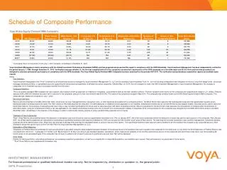
Performance Tables –comparison Linac2/Linac4 Limitations are highlighted in yellow; values to be demonstrated are in italic. Case of 25 ns bunch spacing.
New Linac4 schedule 1. Construction 2. Linac installation, commissioning 3. Reliability run (6 months) 4. Connection and PSB commissioning (7 months) GOAL: all usual beams available in the PSB at start-up 2015
Tentative time line Peak performance out of PS with Linac4