Download
1 / 18
180 likes | 373 Views
Mun Leng Ng Auto-ID Lab @ Adelaide School of Electrical & Electronic Engineering University of Adelaide Australia mng@eleceng.adelaide.edu.au. ANALYSIS OF CONSTRAINTS IN SMALL UHF RFID TAG DESIGN. Introduction on RFID. What is RFID? RFID basic components:. RFID Tag. Consist of

E N D
Mun Leng Ng Auto-ID Lab @ Adelaide School of Electrical & Electronic Engineering University of Adelaide Australia mng@eleceng.adelaide.edu.au ANALYSIS OF CONSTRAINTS IN SMALL UHF RFID TAG DESIGN
Introduction on RFID • What is RFID? • RFID basic components:
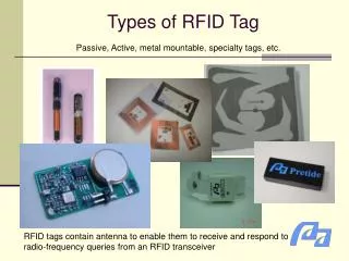
RFID Tag • Consist of • Basic requirement:- Compact- Reliable- Inexpensive
The Constraints • Bandwidth limitation on impedance matching • Tag antenna size constraint towards impedance matching
Application of Bode-Fano Limit on RFID • Allocated bandwidths for RFID: • Others:China: 917 – 922 MHz (Temporary license can be applied)Australia: 918 – 926 MHz
Application of Bode-Fano Limit on RFID • 3 different cases considered:
Application of Bode-Fano Limit on RFID • Assume R = 1 k, C = 1 pF • R = 10 k, C = 1 pF (for less power consuming tag chip in practice)
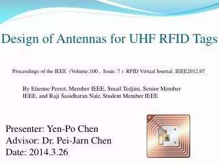
A Simple Loop Antenna • Single-turn circular loop antenna:
Overall Circuit Qant = (2f L)/Rr Qchip = f0/f
Results • When Qant = Qchip: - D = 9.65 cm - Impedance of antenna approximately 5 times impedance of chip • If R = 10 k, C = 1 pF: - D = 4.48 cm - Smaller difference between tag antenna and chip impedances
A Simple RFID Tag Copper foil tuning strap for impedance matching Butterfly antenna (a modified bow-tie)
A Simple RFID Tag (cont) • Simplified equivalent circuit:
Another Simple RFID Tag • Consists of a circular loop antenna with a very simple matching network FRONT REAR