Download
1 / 93
970 likes | 1.17k Views
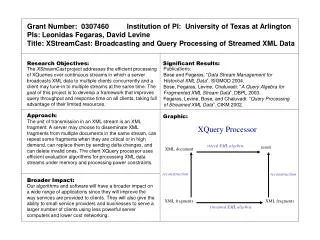
Graphic Hardware. Architecture of Graphics System. Display Processor Memory. Frame Buffer. Video Controller. Monitor. Monitor. CPU. Display Processor. System Memory. System Bus. Basic Graphics System. Output device. Input devices. Image formed in FB.

E N D
Architecture of Graphics System Display Processor Memory Frame Buffer Video Controller Monitor Monitor CPU Display Processor System Memory System Bus
Basic Graphics System Output device Input devices Image formed in FB
IBM Advances inDisplay Technology • In 1981, IBM introduced the Color Graphics Adapter (CGA) display, able to display 4 colors and max resolution of 320x200. • In 1984, Enhanced Graphics Adapter (EGA) display, able to display 16 colors and resolution of 640x350.
IBM Advances in Display Technology (cont.) • In 1987, Video Graphics Array (VGA) display. • Most computers today support the VGA standard. • In 1990, Extended Graphics Array (XGA) display, capable of resolutions 800x600 in true color ( 16.8 million colors) and 1024x768 in 65,536 colors.
Pre-IBM Apple II • Released in 1977 • First true “personal computer” • Based on the Apple I design with some additions • Plastic case • Able to display color graphics • Able to display 6 colors at 280x192 resolution.
Windows Screen Shots Throughout Time: MS-DOS Windows 3.1
Windows Screen Shots Throughout Time: Windows 98 Windows 2K
Pixels Faceplate picture elements (pixels) are formed by depositing and patterning a black matrix, standard red, green, and blue TV phosphors and a thin aluminum layer to reflect colored light forward to the viewer.
Frame Buffers • A frame buffer may be thought of as computer memory organized as a two-dimensional array with each (x,y) addressable location corresponding to one pixel. • Bit Planes or BitDepth is the number of bits corresponding to each pixel. • A typical frame buffer resolution might be • 640 x 480 x 8 • 1280 x 1024 x 8 • 1280 x 1024 x 24
Examples of Pixel Depth Monochrome • Monochrome graphics have one-bit pixel depth. (pure black or pure white)
True Color Display Green • 24 bitplanes, 8 bits per color gun. • 224 = 16,777,216 8 8 8 Red Blue
Examples of Pixel Depth8 Bit Colour • 8 bits per pixel provides 256 colour choices (Typical of the web - that’s why web graphics need some skilful preparation)
Examples of Pixel Depth • 24 or 32 bits per pixel provides thousands or millions of colour choices. (Typical of graphics and games software)
Direct Color Framebuffer • Store the actual intensities of R, G, and B individually in the framebuffer • 24 bits per pixel = 8 bits red, 8 bits green, 8 bits blue • 16 bits per pixel = ? bits red, ? bits green, ? bits blue DAC
Resolution • Resolution refers to the density of dots on the screen or printed image and directly affects quality • The higher the resolution, the less jagged the image. • Resolution is measured in DPI (Dots per Inch) • (The printing industry is largely unmetricated and still uses inches because printing measures such as the Point (1 72nd of an inch) do not easily convert to metric units.) • The higher the resolution, the better the potential output.
Typical Resolutions • Screens generally operate at around 72-100 dpi • Printed images range from 300 to 2400 dpi • Resolution affects the file size of an image. • The higher the resolution, the bigger the file. • The visible resolution is limited to the maximum possible on the output device (screen or printer). • No matter how high the resolution of a photograph, it will show at the resolution of your screen or printer.
Other meanings of resolution • Dot Pitch [Display] - Size of a display pixel, distance from center to center of individual pixels on display • Cycles per degree [Display] - Addressable elements (pixels) divided by twice the FOV measured in degrees. • Cycles per degree [Eye] - The human eye can resolve 30 cycles per degree (20/20 Snellen acuity).
TECHNOLOGIES CATHODE RAY TUBE (CRT) VACUUM FLOURECENT DISPLAY (VFD) FIELD EMISSION DISPLAY (FED) LIQUID CRYSTAL DISPLAY (LCD) PLASMA DISPLAY PANEL (PDP) ELECTROLUMINISCENT DISPLAY (EL) ORGANIC LIGHT EMITTING DIODE (OLED)
VFD Earliest Flat technology Low Cost Excellent Viewing Angle Long Life Matrix Addressing Wire Emitters Cathodoluminescent Mechanical Complexity Low Resolution
Basic Cathode Ray Tube (CRT) Images taken from Hearn & Baker, “Computer Graphics with OpenGL” (2004) Fire an electron beam at a phosphor coated screen
Electron Guns Electron Beams Focusing Coils Deflection Coils Anode Connection Shadow Mask Phosphor layer Close-up of the phosphor coated inner side of the screen
Raster Scan Systems Images taken from Hearn & Baker, “Computer Graphics with OpenGL” (2004) Draw one line at a time
Raster Scan Displays • Picture definition is stored in a memory area called the refresh buffer or frame buffer.
Raster Displays • frame must be “refreshed” to draw new images • as new pixels are struck by electron beam, others are decaying • electron beam must hit all pixels frequently to eliminate flicker • critical fusion frequency • typically 60 times/sec • varies with intensity, individuals, phosphor persistence, lighting...
Monitor Classifications • Monochrome: Display two colors, one for the background and one for the foreground. • Gray-Scale: A special type of monochrome monitor capable of displaying different shades of gray. • Color: Can display anywhere from 16 to over 1 million different colors. Sometimes called RGB monitors.
Colour CRT Images taken from Hearn & Baker, “Computer Graphics with OpenGL” (2004) An electron gun for each colour – red, green and blue
Color CRTs • three electron guns • metal shadow maskto differentiate beams
Color CRTs • three electron guns • metal shadow maskto differentiate beams
Color CRTs • color CRTs much more complicated • requires manufacturing very precise geometry • uses a pattern of color phosphors on the screen: Delta electron gun arrangement In-line electron gun arrangement
Display Technologies • Cathode Ray Tubes (CRTs) • most common display device today • evacuated glass bottle • extremely high voltage • heating element (filament) • electrons pulled towards anode focusing cylinder • vertical and horizontal deflection plates • beam strikes phosphor coating on front of tube
Monitor Quality and Resolution Quality: • Manufacturers describe quality by dot pitch. • Smaller dot pitches mean pixels are closely spaced which will yield a sharper image. • Most monitors have dot pitches that range from 0.22mm to 0.39mm. Resolution: • Indicates how densely packed the pixels are. • Most modern monitors can display 1024x768 pixels. • High end models can display 1280x1024.
ToshibaTM, 42”, Plasma HTDV Flat-Panel Displays (Plasma) Flat-Panel Non-Emissive Emissive LCD DMD Plasma CRT(90°deflected) Active-Matrix LED Passive-Matrix Thin-Filmelectroluminescent
LCD Most mature flat panel technology Major share of FPD market Poor intrinsic viewing angle Requires backlight Slow Effected by Temperature and sunlight
LCD History • Liquid crystals were first discovered in 1888 by Austrian botanist Friedrich Reinitzer. • When cooled, the liquid turned blue before finally crystallizing. • RCA made the first experimental LCD in (1968). • Manufacturers have been developing creative variations and improvements since on LCDs.
LCDs • Liquid Crystal Displays (LCDs) • organic molecules, naturally in crystalline state, that liquefy when excited by heat or E field • crystalline state twists polarized light 90º.
LCDs • transmissive & reflective LCDs: • LCDs act as light valves, not light emitters, and thus rely on an external light source. • laptop screen: backlit, transmissive display • Palm Pilot/Game Boy • reflective display
Liquid Crystal Displays Images taken from Hearn & Baker, “Computer Graphics with OpenGL” (2004) Light passing through the liquid crystal is twisted so it gets through the polarizer A voltage is applied using the crisscrossing conductors to stop the twisting and turn pixels off
Analog VS Digital signal handling • On most graphic card signal goes through DAC (digital to analog converter) to convert to Analog signal. • LCD must convert the signal back to digital to determine which pixel to light.
Disadvantages of LCDs • Response Time • It is much slower. The delay can cause a ghosting effect on images it displays. (Source: TechRepublic.com, PCWorld.com, TouchScreens.com)
Disadvantages of LCDs • Resolution • Displays Native Resolutions (Resolution that it displays best) • Viewing Angle • Smaller, needed to be viewed more directly from the front. • From the side the images on an LCD screen can seem to disappear, or invert colors. • Newer displays that are coming out have a wider viewing angle so this is not as much of an issue as it has been in the past.
LED • Direct view • backlight source
LCD vs CRT flat & Lightweight low power consumption always some light pixel response-time (12-30ms) view angle limitations resolution interpolation required heavy & bulky strong EM field & high voltage true black better contrast pixel response-time not noticeable inherent multi-resolution support
OLED • Organic Light Emitting Diode (OLED) • Kodak scientist Dr. Ching (1970’s) • OLED materials reported in 1987 • Color improvements by 1989 • Becoming a major competetor with today’s LCD/plasma displays