Download
1 / 18
180 likes | 362 Views
Ferrite Tests for Mu2e Beam-Line Extinction Uses. G. Velev Technical Division Magnet Systems Department. Introduction. Ferrite pulsed magnets are commonly used in the accelerator applications kickers – injection, extraction, gap clearing (recently MI) Orbump – beam orbit manipulation

E N D
Ferrite Tests for Mu2e Beam-Line Extinction Uses G. Velev Technical Division Magnet Systems Department
Introduction • Ferrite pulsed magnets are commonly used in the accelerator applications • kickers – injection, extraction, gap clearing (recently MI) • Orbump – beam orbit manipulation • All of them have a low operational duty cycle, practically <1-3% • For Mu2e, an experiment which searches for a μ-e conversion with an unprecedented sensitivity of ~ 10-16 a new type AC dipoles are needed • These dipoles will be used to extinguish the protons at the level of 10-6 -10-7 between the bunches. They should work continuously at 300 kHz ( Bmax = 160 G) and possibly at 5.1 MHz (Bmax ~ 10 G) at 100% duty cycle • In 2009, we started a R&D to select suitable ferrites for these dipoles • Collaboration with Japan, COMET experiment needs similar technology.
Beam cleaning The idea is to synchronize the beam bunches and AC magnetic field 100 ns bunches separated with 1.7 μs gap ~ 600 kHz The bunches are moving on the nodes - 300 kHz More information – Eric Prebys note: http://mu2e-docdb.fnal.gov/cgi-bin/RetrieveFile?docid=709 In time beam Collimator dipole Out of time beam
Beam cleaning: current version In time beam Collimator 300 kHz dipoles 5.1 MHz Out of time beam Dipole Field (G) Time
Ptotal H B-H curve • B = m H, in ferrites m = m(H,T(C), …) • The losses in ferrite core ~ area under the B-H curve • At low frequency - hysteresis loss • At high frequency - eddy current loss B
Ferrite samples Geometry Sample plate Eddy Currents Eddy Currents 10 RTDs Ferrites 200x200x10 mm3 200x200x5 mm3 «1 plate» geometry ferrite 10 mm «2 plate» geometry isolator ferrite 10 mm ferrite Ferrite types: MnZn, NiZn Frequency: 300kHz, 5.1MHz
ANSYS simulation Magnetic flux density @ direction Temperature Distribution
Heating comparison:1 plate vs 2 plates MnZn High eddy currents Low eddy currents
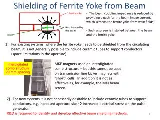
Ferrite selection • Both materials satisfy the criteria for magnet strength • Due to the low resistivity and large eddy current effect, the thickness of MnZn ferrite plates should be ~ 5 mm. • At such high frequencies and power, for MnZn plate we need good insulator between ferrites and power bus - problem with insulation due to corona discharge
Magnet design - x-section • Two designs were considered – magnet with C and H shape of the ferrite plates. IEEE Applied Superconductivity, v. 20, p. 1642.
Current Model Design NiZn Ferrite plates Beam direction
Summary • We measured MnZn and NiZn ferrite samples at 300 kHz and 5.1 MHz. Both materials will satisfy the AC dipole requirements. • Building a magnet prototype based on the selected NiZn ferrites – simple design due to the high resistivity of the material and no-insulation between the ferrites and copper bus • This summer – we plan to test the prototype, including 5.1 MHz • Depending on the result an iteration may be needed. • Contributions: V. Kashikhin, S. Makarov, D. Harding, E. Prebys and PARTI students: I. Iedemska and E. Bulushev.