Download
1 / 9
90 likes | 160 Views
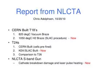
NLCTA Facility Capabilities. E. R. Colby 5/18/09. Ti:Sapphire Laser System. E163 Optical Microbuncher. Cl. 10,000 Clean Room. NLCTA Overview. ESB. Counting Room (b. 225). L-1 (SNS). X-3 (2-pack). E-163. RF PhotoInjector. Gun Spectrometer. 30 feet. Space available for experiments.

E N D
NLCTA Facility Capabilities E. R. Colby 5/18/09
Ti:Sapphire Laser System E163 Optical Microbuncher Cl. 10,000 Clean Room NLCTA Overview ESB Counting Room (b. 225) L-1 (SNS) X-3 (2-pack) E-163 RFPhotoInjector Gun Spectrometer 30 feet Space available for experiments Next Linear Collider Test Accelerator Next Linear Collider Test Accelerator 20 feet S X-0 X-1 X-2 NLCTA capabilities: * S-band Injector producing high-brightness 60 MeV beams (to ~100 pC); ultrashort, ultracold * (4) x-band rf stations and >300 MeV of installed structures * (2) L-band rf stations * Skilled operations group with significant in-house controls capability
Capabilities • Electron Beam (from injector) • 60 MeV, 5 pC, dp/p≤10-4, e~1.5x1.5 mm-mrad, st~0.5 psec • Beamline & laser pulse optimized for very low energy spread, short pulse operation • Laser Beams • 10 GW-class Ti:Sapphire system (800nm, 2 mJ) • KDP/BBO Tripler for photocathode (266nm, 0.16 mJ) • Active and passive stabilization techniques • 5 GW-class Ti:Sapphire system (800nm, 1 mJ) • 100 MW-class OPA (1000-3000 nm, 80-20 mJ) • 5 MW-class DFG-OPA (3000-10,000 nm, 1-3 mJ) • Precision Diagnostics • Picosecond-class direct timing diagnostics • Micron-resolution beam diagnostics • Femtosecond-class indirect timing diagnostics • Picocoulomb-class beam diagnostics • BPMS, Profile screens, Cerenkov Radiator, Spectrometer • A range of laser diagnostics, including autocorrelators, crosscorrelators, profilometers, etc.
NLCTA Laser & LSS • Modest changes required to support EEHG Experiment: • Install evacuated transport line (vacuum components in-hand; pumping is in place) • Install second laser safety shutter (no new logic; add second driver + shutter) • Seek LSC approval for 1-3 micron operation in NLCTA vault and modify SOP
EEHG Experiment and Diagnostics are similar to the E-163 Attosecond Bunching Experiment • Experimental Parameters: • Electron beam • γ = 127 • Q ~ 5-10 pC • Δγ/g = 0.05% • Energy Collimated • εN = 1.5 mm-mrad • IFEL: • ¼+3+¼ period • 0.3 mJ/pulse laser • 100 micron focus • Z0 = 10 cm (after center of und.) • 2 ps FWHM • Gap 8mm • Chicane 20 cm after undulator • Pellicle (Al on mylar) COTR foil
Inferred Electron Pulse Train Structure Bunching parameters: b1=0.52, b2=0.39 Attosecond Bunch Train Generation 800 nm 400 nm l=800 nm First- and Second-Harmonic COTR Output as a function of Energy Modulation Depth (“bunching voltage”) 400 nm 800 nm Left: First- and Second-Harmonic COTR output as a function of temporal dispersion (R56) C. M. Sears, et al, “Production and Characterization of Attosecond Electron Bunch Trains“, Phys. Rev. ST-AB, 11, 061301, (2008).
Machine stability supports sub-picosecond class e/g experiments e.g. This cross-correlation measurement of the electron bunch profile took 5 minutes. Inferred Electron Beam Satellite Pulse sE 800 nm Electron Beam Satellite! I(t) Q(t) 400 nm Much of the visible spread is due to COTR intensity jitter (~Q2) rather than timing jitter
Preliminary Beam Quality Measurement at EEHG Experiment Location 20 pC, 60 MeV,Measured 4/13/09 EEHG Location Measurement Locations • Dispersion measurement was not yet working in downstream linac! Horizontal emittance had significant residual dispersion contribution • Beam at 60 MeV (drifting through all linac x-band structures)
Summary • Existing NLCTA laser systems meet EEHG experimental requirements • Modest extension of the LSS functionality required (shutter+driver) • Laser transport installation required (components in-hand) • Existing NLCTA electron beam quality meets EEHG experimental requirementsat 120 MeV, likely also at 60 MeV, with further machine studies. • Some additional beam diagnostics ahead of the EEHG experiment would speed commissioning • Sub-picosecond-class timing stability has been demonstrated • E-163 experience with near-IR e/g experiments is directly relevant and provides significant leverage • Experience designing experiments and hardware in this low-charge sub-psec regime • Wealth of advanced automated measurement software in LabVIEW and Matlab