Download
1 / 23
250 likes | 579 Views
Alternative Lifeboat Slipway Bearing Materials. Ben Thomas Bournemouth University Thomasb@Bournemouth.ac.uk. Typical Slipway - Padstow. Padstow has recently received a new boathouse in order to accommodate the new Tamar class slip-launched lifeboat

E N D
Alternative Lifeboat Slipway Bearing Materials Ben Thomas Bournemouth University Thomasb@Bournemouth.ac.uk
Typical Slipway - Padstow • Padstow has recently received a new boathouse in order to accommodate the new Tamar class slip-launched lifeboat • The slipway layout is typical of the next generation boathouses and slipways being built for the Tamar • The slipway consists of an upper section of steel rollers and a lower section lined with low-friction 19mm thick jute/graphite infused phenolic resin composite panels 19mm jute/phenolic composite panels Steel rollers
Lifeboat Slipway Recovery - Alignment ropes - Winch cable Lifeboat alignment and attachment of winch cable – alignment ropes and winch cable indicated
Lifeboat Slipway Recovery - Quarter stop ropes - Winch cable Fig. 3.1.2i: Haul Stage – Rope quarter stops and winch cable keel attachment position shown
Tamar Class Lifeboat • The Tamar slip-launched lifeboat is designed as a replacement to the Tyne class lifeboat. It is significantly larger and heavier than the Tyne and this has meant new slipways and boathouses have had to be built to accommodate it. • The Tamar currently operates from new boathouses and slipways at Tenby, Padstow and Cromer
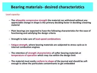
Slipway Lining Materials • Weather Treated Wood – Traditional c.1850 • Nickel/Chromium carbide coated Steel – c.1980 • Jute/Graphite Infused Phenolic Resin Composite – c.1996
Introduction & Previous Work • Research is a continuation of work carried out at Bournemouth university to investigate the suitability of the jute/graphite infused phenolic resin composite as a slipway bearing material for use with the new Tamar class lifeboat • Previous testing used tribometers in conjunction with finite element models and surface analysis to develop an understanding of the friction and wear mechanisms along the slipway • The results of the previous work show that the jute/graphite composite is only marginally suited for use as a slipway lining with the new Tamar lifeboat, with higher that expected friction and wear found • This work looks at the suitability of an alternative, nylon/phenolic resin composite for slipway lining use
Slipway analysis Launch Scenario • It follows that:- • µ max < 0.2 for a 1 in 5 slipway • µ max < 0.167 for a 1 in 6 slipway
Slipway analysis Recovery Scenario • The recovery winch is specified for a pull capacity of 12 tonnes, this means that the maximum friction coefficient during recovery that will meet this requirement on a standard 1 in 5 slipway is: • µ max < 0.150 for a 1 in 5 slipway • µ max < 0.181 for a 1 in 6 slipway • Increasing the winch capacity to 13.7 tonnes in the case of the 1 in 5 slipway will allow the overall friction specification to meet the launch specification at µ max < 0.2
Nylon/phenolic composite vs. Jute/graphite phenolic composite: Material Properties
Nylon/phenolic composite vs. Jute/graphite phenolic composite: Material Properties
Nylon/phenolic composite vs. Jute/graphite phenolic composite: Material Properties
Lubricants Outline • Unlubricated Dry sliding is the simplest way to operate, providing low enough friction and frictional heating can be achieved • Grease Grease lubrication involves the manual application of grease to the slipway before each launch and recovery – this is subsequently washed in to the sea around the base of the slipway where it has the potential to bioaccumulate • Biogrease Biogreases are investigated as a direct substitute for traditional greases with their ability to biodegrade mitigating the bioaccumulation potential • Water Lubrication Water lubrication involves using jets of water mounted at the top of the slipway to run water down the keelway
Nylon/phenolic composite vs. Jute/graphite phenolic composite: Friction Comparison
Conclusions • The new nylon/phenolic composite is shown to meet the friction criteria for all lubricants and at all contact pressures tested • The dry sliding friction is lower than the friction specification which will reduce stick-slip behaviour on the slipway if the lubrication regime breaks down locally • Wear rates are shown to be even and low at all contact pressures tested • The reduced operating temperature of the nylon/phenolic composite compared to the original jute/phenolic composite is likely to increase the chances of reaching the P-V limit at launch if run unlubricated
Recommendations • The new nylon/phenolic composite can be recommended for use on RNLI slipways providing suitable lubrication is provided for cooling to prevent PV limit effects at launch • Water lubrication is shown to be as effective as grease lubrication in reducing friction on the composite and can also be recommended over grease lubrication on cost, environmental and safety grounds • Panel misalignments also play a role in the friction along the slipway and should be reduced to below ~2mm • Fitting a chamfer to slipway panels may help to reduce friction concentrations