CVUT-JBRC Scope
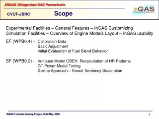
CVUT-JBRC Scope. Experimental Facilities – General Features – InGAS Customizing Simulation Facilities – Overview of Engine Models Layout – InGAS usability EF (WPB0.4) – Calibration Data Basic Adjustment Initial Evaluation of Fuel Blend Behavior

CVUT-JBRC Scope
E N D
Presentation Transcript
CVUT-JBRC Scope Experimental Facilities – General Features – InGAS Customizing Simulation Facilities – Overview of Engine Models Layout – InGAS usability EF (WPB0.4) – Calibration Data Basic Adjustment Initial Evaluation of Fuel Blend Behavior SF (WPB0.2) - In-house Model OBEH Recalculation of HR Patterns GT-Power Model Tuning 2-zone Approach – Knock Tendency Description
CVUT-JBRC Experimental Facilities 4102/120 Testing Engine Engine Features: Compression Ratio: 12 Up to 20 bar BMEP Boost pressure up to 1.4 barg • = 1 (Closed Loop) or Lean Burn VGT Cooled EGR up to 20 % Test Bench Equipment: DC Dynamometer Complete DAQ Gas Analyzers – Exhaust / Intake TPA (Cylinder, Turbine – Inlet/Outlet) Instantaneous Speed – Engine, Turbo Knock Recognition/Quantification
CVUT-JBRC Experimental Facilities On-line Controllable Delivery of Max. of 2 Fuel Additives into Intake Manifold TNG Additional Fuel A SetPoint Feedback Test Bench Computer Additional Fuel B
CVUT-JBRC Experimental Facilities 4 102/110 Engine • Engine features: • Compression Ratio: 10 • Low BMEP • Low Boost Pressure • Uncontrolled Turbocharger • = 1 (Closed Loop) or Lean Burn No EGR Experimental Equipment: AC (W-E) Dynamometer (No Closed Loop Control) Complete DAQ TPA (Intake/Cylinder/Exhaust “Close to Cylinder” Arrangement) Controllable Delivery of Fuel Additives (Sampling of Working Substance from Cylinder during Compression Stroke) Appropriate for: Emulation of “Low Cost” Version; “Steady State” Knock; Preliminary Testing;
CVUT-JBRC Simulation Means OBEH (= CYCLE) – In-House Engine Working Cycle Model Source Code Written in FORTRAN (DOS Based) 0-D Description of Working Substance Behavior Inside the Cylinder by Differential Equations Description of Engine Manifold and Accessory (Including Turbo) by Algebraic Equation Inertia of Gas Bulk Flows NOT Involved Basics: HR Description by Vibe’s Function Czallner – Woschni Recalculation Formulas Heat Transfer Selectable Woschni’s and/or Eichelberg’s Dedicated Among Other for Use in Education Activities Supplements: Temperature of Unburned Zone & Ignition Lag Automated Tuning/Optimization – Pre & Post Processing (Excel-Based) In-House HR Recalculation Routine
CVUT-JBRC Simulation Means GT-Power – Commercial Engine Model (JBRC = Official Partner of Gamma Technologies) Version: 6.2 1-D Engine(s) Geometry Imposed According to Physical Reality 102/120 Engine => Turbine & Compressor Maps Obtained from TC Manufacturer Calibration Data: Set of Engine Integrated Parameters Angle-Resolved Patterns of: In-Cylinder Pressure Manifold Pressure Turbo Speed
Knock Evaluation Model Calibration CVUT-JBRC Simulation Means Knock Recognition/Quantification Routine Experimental Verification Experimental Data
CVUT-JBRC OBEH – HR Recalculation Strategy OBEH – Recalculation of HR Pattern for Various Operational Conditions fi,gi and hi are polynomial functions of: Air excess Pressure and temperature at 60° bTDC Residual gas (+EGR) fraction (?) Ignition timing Engine speed Proven Usable for Various Fuel Compositions Providing: Reference cycle for Given Fuel is Available Implemented into GT-Power Simulation
CVUT-JBRC GT-Power Model Layout Three Pressure Analysis – TPA (Single Cylinder Model 4102/110) Measured In-cylinder Pressure Measured Exhaust Port Static Pressure Measured Intake Port Static Pressure Sampled TPA Outputs pcyl, Tcyl, Tunb, Tburn, mcyl, Mass fractions
CVUT-JBRC GT-Power – TPA Calibration Three Pressure Analysis – Results 1600 rpm, = 1, W.O.T.
bmep = 2.1 bar bmep = 10.2 bar CVUT-JBRC GT-Power – TPA Calibration Three Pressure Analysis – Results – 1600 rpm, = 1
CVUT-JBRC GT-Power - Layout 4102/120 Engine Model
CVUT-JBRC GT-Power – Calibration Engine model CalibrationFull Load Curves, VTG margins, Lean Burn min rack pos. max rack pos.
CVUT-JBRC GT-Power – Calibration Engine model CalibrationFull Load Curves, VTG margins, = 1 cylinder intake manifold
CVUT-JBRC GT-Power Calibration TPA Results 4102/120 Engine
Various types of knock models- chemical mechanism - empirical induction-time correlations Autoignition occurs whenCalls for: Empirical relations for induction time for methane (Constants A and B) Definition of end-gas temperature is crucial (Angle-Resolved Pattern of T) CVUT-JBRC Knock Description
CVUT-JBRC Knock Description CHEMKIN3 Calculation (GRI-Mech3.0 Reaction Mechanism - 53 components/325 reaction)
CVUT-JBRC Knock Description • End Gas Temperature Determination • Direct GT-Power Output • OBEH Output – Calculation Routine Based on 1st Law of Thermodynamics Uses Layer Thickness and its Heat Conductivity • Simplified Two-Zone Mean Temperature Model (Brunt, SAE Paper 981 052): • g=1.338-610-5.T+1 10-8.T2