Download
1 / 21
320 likes | 739 Views
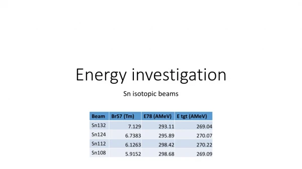
Investigation of Single Conductor Energy Transmission. Presented by Yan Duan Jan 10 th 2013. Supervisor: Dr. Wilsun Xu. Background.

E N D
Investigation of Single Conductor Energy Transmission Presented by Yan Duan Jan 10th 2013 Supervisor: Dr. WilsunXu
Background • Proposed by Nicola Tesla in the beginning of last century, single wire power transmission was thought to be the future of the power transmission system, but was quickly abandoned after Tesla passed away. • As the circuit model of single wire transmission line involves an open circuit instead of a closed one for a conventional two wire system, conventional model can not interpret this phenomenon, thus here I use theory of electromagnetics to try to give explanation for it. • Two wire to one wire-significant economic benefits.
Background • In this presentation, I’ll have a brief look of 2 possible single wire systems that are actually not what we desire, then I’ll focus on the EM theory to interpret this phenomenon, with both qualitative explanation and quantitative derivations. • Finally two possible applications that this research suggest would be discussed in details.
1. Single Wire Earth Return • Equally safe, more reliable, less costly, but with slightly lower efficiency than conventional lines . • Implemented successfully in rural areas in Australia and New Zealand for many years. • However…it simply uses the ground to be the return wire, thus it’s still a closed circuit. For sure not what we’re looking for.
2. Avramenko’s Fake Solution • Left circuit: DC/AC converter. • Right circuit: “Avramenko’s plug”.
3. A view from EM Theory • Regard a single wire as a wave guide. • From basic wave mechanics, if energy can be contained along a single line, then a best way to do this is to form a standing wave on it and thus the two ends of the single line are fixed. In EM, to “fix” a single wire we simply need two perfect conductors on the ends:
A qualitative explanation • Solve the EM wave equation for the electric field part: • Assume a plane wave solution • incident and reflected waves can combine as • Standing wave!
A quantitative derivation • Maxwell’s equations: • Let • Rearrange the terms: • Separation of variables: • electric and magnetic fields depending on mode number pairs: m and n • "transverse electric" TEmn mode, "transverse magnetic" TMmn mode and "both transverse" TEMmn mode.
A quantitative derivation • A quantitative derivation of standing wave starting from a conventional coaxial line model, since a single wire is basically a coaxial line with b equals infinity
A quantitative derivation • Ampere's law: • the characteristic impedance for TEM mode: • For a homogeneous plane wave in free space, there is an intrinsic impedance: • Thus total admittance:
A quantitative derivation • It can be proved that in coaxial line, only TEM00 and TM00 modes are possible: • for a single wire, b is infinity, thus YTEM approaches 0. • Therefore there must exist a single pure TM mode for single wire. • Generally TM mode has a sin form, with perfect conductors, a standing wave! • Consistent with our qualitative derivation above.
Two problems • Basic wave mechanics tells us that: • if we have a typical frequency of 60Hz and assume the EM wave is propagating with speed of light: • Furthermore, at low frequency, even if we assume that such a long distance transmission is needed:
Two problems • Gauss’s Law gives us: • Solutions of Laplace's equation in cylindrical coordinates show that the capacitance per unit length of a single wire at a height h above the ground is given by: • If we take a=1cm, a typical value for such a long distance of V=300kV, then at height h=10m, the electric field E=7894V/m, compared with the two wire system with distance of 2m between two wires, whose E is less than 1000V/m, this electric field is too strong. • Hazardous issue.
Two problems • However, for high frequency signals, not only the transmission distance could be reduced to only several kilometers, but also as Sommerfield proved in 1899, “a single cylindrical conductor (wire) to propagate radio frequency energy as a surface wave”, thus the EM field can be constrained near the surface of the single conductor, and no hazardous issues will be caused. The only problem is the radiation loss of the signals at high frequency. • Although high frequency waves are not suitable to transfer power, but it’s indeed practical to transmit information/signal using a single wire.
4. Goubau Line (“G-Line”) • Following Sommerfield’s surface wave idea, in 1950, Goubau registered a patent, the so-called “G-line” . • A single conductor coated with a layer of dielectric. • Two metal cones act as wave launcher and receiver, which have a diameter equal to wavelength.
Two Applications from G-Line • It's possible to make use of the pre-existing power distribution grid to do "power line communication" instead of "power line transmission". • The actual method is just to implement two same cone-shaped devices as launcher and receiver in G-Line on a single wire of a power grid, then information signal can be excited by the launcher and received by the receiver.
Tesla's world wireless system • Back to the beginning of twentieth century, Tesla proposed a great power distribution plan that, if around the Earth people can build about 5 power towers, or he named "Wardenclyffe Tower"
Tesla's world wireless system • How come could this "wireless" be possible? • If we go back to the Goubau Line model, we realize that the "G-line" part is simply a single conductor coated with dielectric material, with its two end connected to two cone-shaped wave launcher or receiver. • What if we regard the Earth as the conductor? • And our atmosphere as the dielectric?
Tesla's world wireless system • what if we replace the cone-shaped launcher/receivers with two metal balls for more practical reason? We got this: • thus Wardenclyffe Tower could have been regarded as a big "wave launcher", which consists of a metal ball and a coil to transfer energy. • Therefore, the Goubau Line model shows us that the imaginary "world wireless system" is indeed feasible, as long as the radio frequency can be tuned to satisfy the equation:
Summary • Thanks for the support from Dr. Xu, Dr. Jean-Paul, and Mr. Alaei, and all your kind attendance. • Questions?