Download
1 / 31
320 likes | 513 Views
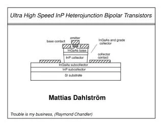
Characterization Presentation Spring 2008. Ultra High Speed Signal Card. High Speed Digital Systems Lab Spring 2008 Students: Jenia Kuksin Alexander Milys Instructor: Yossi Hipsh. Table of Contents. Project Overview Main Goal Experiment Array

E N D
Characterization Presentation Spring 2008 Ultra High Speed Signal Card High Speed Digital Systems Lab Spring 2008 Students: Jenia Kuksin Alexander Milys Instructor: Yossi Hipsh
Table of Contents • Project Overview • Main Goal • Experiment Array • Experiments Requirement from students. • Scope of Experiments • System in more details • Examples from final “Student Workbook” • Time Schedule • Conclusions(Expectations)
Project Overview Defining and building equipment for high speed phenomena experiment, which allow students to understand all phenomenon and master in this field. Equipment will contain ultra high speed driver and array of transmission lines onboard. There will be 88 different experiment which can be chose.
Main Goal • Building a new evaluation system for the HSDSL laboratory. • Learning System Integration Techniques. • Understanding High Speed Signal Phenomena. • Learning techniques for very high speed hardware implementation. • Learn a PCB design process.
Board Controller Switching System Pulser Transmission Lines Array Experiment Environment Instructor Student
System in more details Controller S3 Connects One channel from 36 To scope S2 Connects One channel from 36 To scope S0 0narrow pulse 1wide pulse S1 Will be OE for splitters Analog Switches Analog Switches Pulser Signal Splitter Z(Source) Transmission Lines 36 lines Termination Z(Load) 1 36 36 36 S5 Control for MCP195 (jitter)
Reflection Phenomena Reflection is a well-studied transmission line effect. In high-speed system, reflection noise increases time delay and produces overshoot, undershoot and ringing.The root cause of reflection noise is the impedance discontinuity along the signal transmission path. Crosstalk Due to electromagnetic coupling between signal traces and vias. Jitter Jitter refers to deviation in time between edges of individual signals that are periodic. Skew Skew is the difference between two or more signals in their delay at a specified voltage threshold. Scope of Experiments
Electrical schematics of experiments
Match to Match Zo Zo Zo Zo Z=0 Zo Zo Zo Zo Z ∞ Z ≠Zo Zo Electric field Electric field Electric field Electric field Reflection Phenomena Match to Short Match to Open Match to Mismatch
Zin≠Zo Z=0 Zo Zin≠Zo Zin Zin≠Zo Zo Z ∞ C Zo Zout ≠Zo Zo Electric field Electric field Electric field Electric field Reflection Phenomena Mismatch to Open Mismatch to Short Mismatch to Mismatch Match to Capasitor
L Zo Zin Electric field Reflection Phenomena Match to Inductance
Zo L1 Zo M2 Zo Zo Zo Electric field Crosstalk Crosstalk, caused by EM coupling between multiple transmission lines running parallel, is also a well-studied subject in Electromagnetic. It can cause noise pick up on the adjacent quiet signal lines that may lead to false logic switching. Crosstalk will also impact the timing on the active lines if multiple lines are switching simultaneously.
MC10EP195 Digital Control Delay Jitter
Jitter implementation LUT Digitally Controlled Delay Signal output Signal input Controller Outer project (Mony Group) MC10EP195 MC10EP195 (ECL standard) device perform time delay for a signal. Devise can be programmed to provide time delays for the signal in a range of 2.2ns-12.2ns with 10ps resolution. LUT will contain data for multiple gitter implementation (sinus, Gaussian…)
Short pulse (delta) Long pulse (step) Function selection Pulse Generator Specifications definition OUTPUTS • Short pulse width: 0.5 to 1 nSec • Long pulse width: 10 to 13 nSec • Rise/fall Time : ~250 pSec • Pulses repetition: 0.1-1 µSec (1-10 MHz) INPUTS • Function selection: • Control of the pulse width: 10pSec steps Programmable Fast Pulse Module
Pulse Generator - Block diagram Translator MC100EPT20 3.3V ECL Programmable Delay Chip Splitter MPC94551 MC100EP195 3.3V / 5V ECL 2-Input Differential AND/NAND One Shot MC74LCX74DG Oscillator 10MHz C01025 11 MC100EP05 CMOS 5V/3.3V CMOS 3.3V Translator MC100EPT20 3.3V ECL Programmable Delay Chip MC100EP195 11 Controller 3
Splitter Driver_2 Driver_3 Driver_1 Splitter will duplicate the signal from the original “Fast Pulser” and connect it to all transmission lines. Driver_1, Driver_2, Driver_3 are components of a Splitter module. All transmission lines get their signals from a driver. As can be seen Splitter block is split to three sub blocks, and can be recognized by source impedance.
Analog switch Those are switches that will allow to choose a specific transmission line from the set. Switches will allow to connect a chosen experiment to the Scope. *Switches will chose one of 36 lines. Sw_in Sw_out
Requirement from student • Student will be asked to measure voltage amplitude and time parameters of the signal which is shown on the scope. • Student has to capture screen from the scope and insert it to final report in Word document.
Digital Oscilloscope Characterization • Hardware Analog Bandwidth (-3 dB)≥1.4 GHz • Sample Rate≥2.8 GS/s • Input Channels4
Experiment description, as they will appear in final booklet for students.
Conclusion • Final system will allow future students to get familiar with HSD signals, understand all phenomenon and master in this field.