Download
1 / 35
360 likes | 509 Views
A Time-Scale Analysis of Opposed-Flow Flame Spread – The Foundations. Subrata (Sooby) Bhattacharjee Professor, Mechanical Engineering Department San Diego State University, San Diego, USA. Acknowledgement. Profs. Kazunori Wakai and Shuhei Takahashi, Gifu University, Japan

E N D
A Time-Scale Analysis of Opposed-Flow Flame Spread – The Foundations Subrata (Sooby) Bhattacharjee Professor, Mechanical Engineering Department San Diego State University, San Diego, USA
Acknowledgement • Profs. Kazunori Wakai and Shuhei Takahashi, Gifu University, Japan • Dr. Sandra Olson, NASA Glenn Research Center. • Team Members (graduate): Chris Paolini, Tuan Nguyen, Won Chul Jung, Cristian Cortes, Richard Ayala, Chuck Parme • Team Members (undergraduate): Derrick, Cody, Isaac, Tahir and Mark. (Support from NASA and Japan Government is gratefully acknowledged)
Overview • What is opposed-flow flame spread? • Flame spread in different environment. • Mechanism of flame spread. • Length scales and time scales. • Spread rate in normal gravity. • Spread rate in microgravity • The quiescent limit
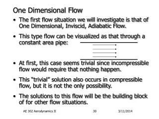
Upward or any other flow-assisted flame spread becomes large and turbulent very quickly. Opposed-flow flame spread is also known as laminar flame spread.
Downward Spread Experiment, SDSU Combustion Laboratory PMMA: = 10 mm = 0.06 mm/s AFP: = 0.08 mm = 1.8 mm/s
Sounding Rocket Experiment Spread Over PMMA: Infrared Image at 2.7m mm • Gravity Level: 1.e-6g • Environment: 50-50 O2/N2 mixture at 1.0 atm. • Flow Velocity: 50 mm/s • Fuel: Thick PMMA (Black) • Spread Rate: 0.45 mm/s
Experiments Aboard Shuttle: O2: 50% (Vol.), P=1 atm. Image sequence showing extinction Fuel: Thin AFP, =0.08 mm = 4.4 mm/s Vigorous steady propagation. Thick PMMA
Mechanism of Flame Spread O2/N2 mixture Fuel vapor Virgin Fuel The flame spreads forward by preheating the virgin fuel ahead.
Mechanism of Flame Spread O2/N2 mixture Vaporization Temperature, Virgin Fuel The rate of spread depends on how fast the flame can heat up the solid fuel from ambient temperature to vaporization temperature .
Forward Heat Transfer Pathways: Domination of Gas-to-solid Conduction (GSC) The Leading Edge Gas-to-Solid Conduction Pyrolysis Layer Preheat Layer Solid-Forward Conduction
The Leading Edge Length Scales Gas-phase conduction being the driving force,
Energy Balance: Characteristic Heating Rate Sensible heating (sh) rate required to heat up the unburned fuel from to Flame Temperature, Vaporization Temperature, Heating rate due to gas-to-solid (gsc) conduction: Ambient Temperature,
Thick Fuel Spread Rate from Energy Equation Flame Temperature, Conduction-limited or thermal spread rate: Vaporization Temperature, For semi-infinite solid,
Thin Fuel Spread Rate from Energy Equation Flame Temperature, Conduction-limited spread rate: Vaporization Temperature, For thermally thin solid,
Parallel Heat Transfer Mechanisms Gas to Environment Radiation (ger) Gas to Solid Radiation (gsr) Solid to Environment Radiation (ser) Gas to Solid Conduction (gsc) Solid Forward Conduction (sfc)
Time Scales Relevant to Gas Phase Gas to Environment Radiation (ger) Available Time
Time Scales Relevant to Gas Phase: Thermal Regime Solid to Env. Radiation (ser) Gas to Solid Radiation (gsr) Available Time in Gas Phase
Time Scales Relevant to Solid Phase Available Time
Time Scales Relevant to Solid Phase: Thermal Regime Available Time
Time Scales – Gas to Surface Conduction The characteristic heat is the heat required to raise the solid-phase control volume from to . Gas to Solid Conduction (gsc) Gas-to-surface conduction time:
Thermal Regime: Spread Rates Using Time Scales Gas to Solid Conduction (gsc) Substitute the two limits of
Relative dominance of GSC over SFC Gas to Solid Conduction (gsc) Solid Forward Conduction (sfc)
Radiative Term Becomes Important in Microgravity Solid to Environment Radiation (ser) The radiation number is inversely proportional to the velocity scale. In the absence of buoyancy, radiation can become important. Gas to Solid Conduction (gsc) Solid Residence Time:
Spread Rate in the Microgravity Regime Solid to Environment Radiation (ser) Include the radiative losses in the energy balance equation: Gas to Solid Conduction (gsc) Algebraic manipulation leads to:
Mild Opposing Flow: Computational Results for Thin AFP As the opposing flow velocity decreases, the radiative effects reduces the spread rate
The Quiescent Microgravity Limit: Fuel Thickness Solid to Environment Radiation (ser) The minimum thickness of the heated layer can be estimated as: Gas to Solid Conduction (gsc) All fuels, regardless of physical thickness, must be thermally thin in the quiescent limit.
The Quiescent Microgravity Limit: Spread Rate Solid to Environment Radiation (ser) The spread rate can be obtained from the energy balance that includes radiation. Gas to Solid Conduction (gsc) reduces to: where,
The Quiescent Limit: Extinction Criterion In a quiescent environment steady spread rate cannot occur for
The Quiescent Limit: MGLAB Experiments Extinction criterion proposed is supported by the limited amount of data we have acquired thus far.
Conclusions • A phenomenological model for opposed flow flame spread is built around two residence times, one in the gas phase and one in the solid. • Theoretical solutions in the thermal regime are reproduced using the time scale analysis. • Deviation from the thermal regime can be quantified by comparing the time scale of the added physics with the appropriate residence time. • In the quiescent microgravity environment all fuels behave like thin fuels. • A critical thickness is proposed beyond which a spreading flame cannot be sustained in such environment.