Download
1 / 1
10 likes | 82 Views
Develop a mathematical model for vaporisation rate in sub-critical turbulent flow. Assess model using test cases with varied injection scenarios. Explore advantages of parallel computing for simulations.

E N D
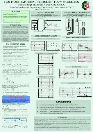
Liquid Supply Honeycomb 500 High pressure vessel Test Section Spray nozzle Ø40 Ø64 Air Outlet Ø200 Electric heater Cooling Trap All dimensions in mm FLAT BED ATOMISER 30 25 10 Ø5 FLOW DIRECTION 0.1 20 Ø5 150 TURBULENCE GENERATOR • OBJECTIVES • To develop a mathematical model for the vaporisation rate in a sub-critical turbulent flow. • To assess this model using selected test cases providing measurements for different injection scenarios, fuels, pressures and temperatures. • To explore advantages offered by parallel computing environment for this type of simulations. TEST CASE1: PREMIX DUCT, Measurements of Brandt et al. (1998). flat-bed prefilming atomiser, strong turbulence, kerosene Jet-A in air, widely varied high pressure and temperature. TEST CASE2: SPRAY IN A HEATED STREAM, Measurements of Sommerfeld & Qui (1998). Hollow-cone atomiser, moderate turbulence,iso-propyl alcohol in air, atmospheric pressure, varied temperature. TWO-PHASE VAPORISING TURBULENT FLOW MODELLINGMandeep Singh SIDHU and Alexey A. BURLUKA,School of Mechanical Engineering, University of Leeds, Leeds, LS2 9JTA.A.Burluka@leeds.ac.uk • INTRODUCTION • Industrial liquid-gas flows often involve vaporisation of liquid in variable temperature, high-pressure, strong-turbulence environment. • Mathematical description must take into account nonlinear coupling between mass-, momentum-, and energy-transfers. • In a sub-critical flow, the rate of phase change from liquid to gas is proportional to the liquid surface area. Hence, a pre-requisite for the vaporisation description is an accurate description of atomisation. • Applications where the liquid is injected at a temperature lower than that of the surrounding gas, so that the vaporisation rate is determined by the heat transfer from the gas by conduction and convection. • Vaporisation rate per unit area of the liquid surface is influenced by thermodynamics (pressure, temperature, liquid properties, mass fraction of vapour etc.) and fluid dynamics (average motion as well as turbulent fluctuations). ALL DIMENSIONS IN MM MODEL ASSESSMENT: RESULTS MODEL ASSESSMENT: RESULTS FLOW FIELD : MEAN AND RMS VELOCITY FLOW FIELD : MEAN AND RMS VELOCITY • Σ-Yliq ATOMISATION MODEL • The only model capable of describing the atomisation process from the first principles • Proved to describe qualitatively and quantitatively effects of injection regimes, gas, and liquid properties on atomisation in a flow without vaporisation (Beheshti et al., Theor. Comp. Fluid Dyn, vol. 21, 2007) • Developed for large Reynolds and Weber numbers (Vallet et al., Atomisation and Sprays, vol. 11, pp. 619-642, 2001). • Entirely Eulerian framework; both liquid and gas together are treated a single continuum, hence, existing numerical algorithms, e.g. PISO or SIMPLE, can be used. • Dispersion of the liquid is found from a transport equation for the average liquid mass fraction: VAPORISATION RATE : PRESSURE EFFECTS SMD PROFILES • Atomisation, that is a rapid generation of the liquid surface area, is determined from the transport equation for the average area of liquid-gas interface per unit mass of the two-phase medium: TEMPERATURE EFFECTS DROPLET MASS FLUX PROFILES VAPORISATION MODEL VAPORISATION OF A DROPLET INVOLVES HEAT AND MASS TRANSPORT, FLUID DYNAMICS, AND FOR FLOWS WITH COMBUSTION, CHEMICAL KINETICS. RATE OF VAPORI-SATION IS AFFECTED BY NUMEROUS FACTORS, AMONG WHICH ARE THE RELATIVE MOTION BETWEEN A DROPLET AND GAS, PRESSURE AND TEMPERATURE CHANGES. • CONCLUSIONS • A new expression is proposed for vaporisation rate in turbulent flows. • This expression describes experimentally observed vaporisation enhancement with increasing rms velocity, temperature and pressure for very different flows. • Used with Σ-Yliq atomisation model, it allows description of both atomisation and vaporisation within a unified simple framework. • REFERENCES • M. Brandt, M. Rachner and G. Schmitz, Experimental and numerical study of kerosene spray evaporation in a premix duct for gas turbine combustors, Comb. Sci. Tech., vol. 138, pp. 313-348, 1998. • M. Sommerfeld and H.H. Qiu, Experimental Studies Of Spray Evaporation In Turbulent Flow, Int. J. Heat and Fluid Flow, vol. 19, pp. 10 – 22, 1998. • I. Gokalp, C. Chauveau, C. Morin, B. Vieille and M. Birouk, Improving droplet breakup and vaporisation models, including high pressure and turbulence effects, Atomisation Sprays, vol. 10, pp. 475-510, 2000. • A. Vallet, R. Borghi and A.A. Burluka, Development of an Eulerian model for the atomisation of a liquid jet, Atomisation Sprays, vol. 11, pp. 619-642, 2001. • S.S. Sazhin, Advanced Models Of Fuel Droplet Heating And Evaporation, Progr. Energy Comb. Sci., vol. 32, pp. 162-214, 2006. • N. Beheshti, A.A. Burluka and M. Fairweather, Assessment of Σ – Yliq model predictions for air-assisted atomisation, Theor. Comp. Fluid Dyn., vol. 21, 2007 (to appear).


