Download
1 / 60
600 likes | 772 Views
The Quest for Ultra-Short X-ray Pulses. Alexander Zholents ANL. Fermilab , 03/09/2011. J. Levesque and P.B. Corkum , Can. J. Phys. 84: 1–18 (2006) . 2010. X-ray pulses. Thomson. Slicing. SPPS. LCLS. Expected.

E N D
The Quest for Ultra-Short X-ray Pulses Alexander Zholents ANL Fermilab, 03/09/2011
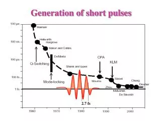
J. Levesque and P.B. Corkum, Can. J. Phys. 84: 1–18 (2006) 2010 X-ray pulses Thomson Slicing SPPS LCLS Expected “…shorter and shorter laser pulses were obtained since discovery of mode locking in 1964. Each advance in technology opened a new field of science and each advance in science strengthened the motivation for even shorter laser pulses.”
Femtochemistry Ahmed Zewail, Nobel Prize, 1999 Scientific drivers. Why ultra-short pulses? • Phase transitions in solids • Surface dynamics • Making and braking of bonds during chemical reactions • Chemical dynamics in proteins • Correlated behavior of electrons in complex solids … for showing that it is possible with rapid laser technique to see how atoms in a molecule move during a chemical reaction t ~1Å / (speed of sound) ~ 100 fs • The vibration period between the two hydrogen atoms in a hydrogen molecule is about 8 fs
C N H … and after absorption of a photon First step in vision1) How living systems function using smallest amount of energy? Molecule of rhodopsin before … 1) R.W. Schoenlein, L.A. Peteanu, R.A. Mathies, C.V. Shank, Science, 254, 412 (1991).
Probe valence electrons with optical laser Probe core electrons with x-rays In 1981 Charles Shank and coworkers at Bell Labs redefined the term “ultrafast” when they reported the demonstration of 90 fs long pulses from colliding-pulse dye laser 1 Charles Shank 1) R.L. Fork, B.I. Greene, C.V. Shank, Appl. Phys. Lett., 38, 671(1981).
Laser assisted techniques: 90o Thomson scattering1 300 fs 1) S. Chattopadhyay, K.-J. Kim, C. Shank, Nucl. Instr. Meth.,A341, 351 (1994). 2) R.W. Schoenlein et. al., Science, 274(11), 236 (1996).
90oThomson scattering(2) Lattice expansion dynamics in InSb as a function of time delay between laser and x-ray pulses1 X-ray probe before the laser pump X-ray probe after the laser pump 300 fs 1) A.H. Chin, R.W. Schoenlein, T.E. Glover, P. Balling, W. P. Leemans, C. V. Shank, “Ultrafast Structural Dynamics in InSb Probed by Time-Resolved X-Ray Diffraction”, Phys. Rev. Lett. 83, 336 - 339 (1999).
Femtosecond Laser ~50 W First Light 2000 In-vacuum Undulator Femtosecond X-ray Beamline “Slicing” source of fs x-ray pulses at the ALS1 100 fs electron slice 100 fs laser pulse 100 fs x-ray pulse synchronous to laser lW 70 ps electron bunch spatial separation by dispersive bend wiggler undulator beamline Laser - ebeam interaction in wiggler 1) R.W.Schoenlein et al , Science, March 24, (2000)
Light interaction with relativistic electron*) - S e N Elaser energy modulation over the length of one optical cycle S light N N S N S l u V E B k k E B V Energy modulation of electrons in the wiggler magnet by the laser light = B B sin( z k ) u 0 Magnetic field in the wiggler Electron trajectory through wiggler FEL resonance condition Laser wavelength Wiggler period While propagating one wiggler period, the electron is delayed with respect to the light on one optical wavelength *) Motz 1953; Phillips 1960, Madey 1971
Alternative approach to find energy modulation Far field observer spontaneous emission laser Far field observer sees the field: Electron beam spontaneous emission laser Interference term defines energy gain/loss
Selection of fs x-ray pulses Electron beam energy modulation DE 2sE z 100 fs DX Radiation of these electrons is selected 2sx In dispersive place DX=D•DE/E z 100 fs
Selection of fs x-ray pulses1 electron bunch subps x-ray pulse laser pulse mask bend magnet wiggler undulator Other means to select fs pulse besides coordinate separation angular selection Select before first x-ray mirror BESSY: courtesy S. Khan +d time-off-flight selection -d spectral selection (works only with undulator source)2 Bandwidth of the undulator radiation at a high harmonic number n 1) R.W. Schoenlein, et al., Appl. Phys.B71, 1 (2000). 2) H. Padmore, private discussion
350 s = 16.6 ps 300 250 P M T # photons 200 150 bend magnet visible radiation 100 50 0 fs pulse fs pulse delay (ps) 60 -60 -40 -20 0 20 40 Diagnostics Measurement of a short pulse of synchrotron radiation via cross-correlation with a short laser pulse Ti:Sa laser Ti:Sa amplifier hn1 = 1.55 eV hn=hn1+hn2 e-beam hn2 = ~2 eV light BBO filter e- slit intermediate focus
-3sx to +3sx 2500 Electron Density Distribution counts 2000 -1500 -1000 -500 0 500 1000 1500 250 x/sx 200 counts 150 100 -1200 -1000 -800 -600 -400 -200 0 200 180 -0.3 time (ps) 0.3 160 140 counts 120 100 80 60 200 -1200 -1000 -800 -600 -400 -200 0 delay (fs) Diagnostics (2) ALS bend magnet beamline +3sx to +8sx +4sx to +8sx Modulation amplitude extracted from experimental data is 6.4 MeV (expected ~ 10 MeV)
Diagnostics (3) Deducing energy modulation amplitude from beam lifetime measurements using scraper in dispersive location (BESSY) Energy modulation amplitude versus laser pulse energy Electron loss rate versus scraper position theory experiment with laser without laser laser pulse energy, (mJ) scraper position, (mm) courtesy S. Khan Approximately two times more laser pulse energy was used than it was predicted (same problem at ALS) Not explained so far !
with laser photons/(s 0.1% bw) signal-to-background signal/background e without laser pump pulse x-ray angle, (mrad) Detected photon rate per 0.1% bandwidth versus cutoff angle “Slicing” at BESSY 1) 1) S. Khan, et al.,PRL, 97, 074801 (2006)
Small-signal FEL gain 5 laser 4 s = 16.6 ps 3 e-beam gain (x10-3) Gain follows peak current distribution 2 laser spectrum gain function 1 Gain, % 0 l1 -60 -40 -20 0 20 40 60 80 l2 delay (ps) FEL resonance electron bunch laser pulse wiggler detuning form FEL resonance I ≈ 25A Measurement of FEL gain through wiggler at ALS Madey’s theorem FEL gain ~ measured with laser oscillator 0.4 0.2 bunch train and a gap
Laser-induced coherent fs THz radiation1-4 1.2 first turn 0.4 Relative charge density Amplitude (arb. units) 1.04 second turn 0.92 time (ps) frequency (THz) e-beam density distribution e-beam density distribution x/sx Large, medium and small modulation amplitudes -0.3 time (ps) 0.3 Dip in the electron density distribution expands and dries out as the electron bunch travels along the ring • R.W.Schoenlein et al , Appl. Physics, B71, 1 (2000). • J. Byrd et al , Phys. Rev. Lett., 96, 164801(2006). • K. Holldack et al , Phys. Rev. Lett., 96, 054801 (2006). • J. Byrd et al , Phys. Rev. Lett., 97, 074802 (2006).
Dip reconstruction from THz spectra1 electron density, (arb. units) Pcoh/Pinc, (arb. units) wave number, (1/cm) time, (ps) THz signal is now routinely used for tuning of laser e-beam interaction and to maintain it with a feedback on mirrors – BESSY, ALS, SLS 1) K. Holldack et al , Phys. Rev. Lett., 96, 054801 (2006).
Alternative approach to find energy modulation* Black: measurement Red: theoretical fit Laser Spontaneous emission An example of a poor overlapping: wiggler is detuned too far away from the laser frequency In the experiment, wiggler gap was adjusted such as to change the central frequency of spontaneous emission from 200 nm to 1000 nm laser *) A. Zholents, K. Holldack, Proc. FEL’06, Berlin (2006).
High repetition rate source of ps x-ray pulses1,2 Radiation from tail electrons angle >> beam divergence + x-ray diffraction ~1 ps undulator Radiation from head electrons Storage Ring Ideally, second cavity cancels effect of first cavity Deflecting cavity delivers a time-dependent vertical kick to the beam Trading brightness to a short pulse Compression using asymmetrically cut crystal • A. Zholents, P. Heimann, M. Zolotorev, J. Byrd, NIM A,425, 385 (1999). • M. Katoh, Japan. J. Appl. Phys, 38, L547(1999)
Application to the Advanced Photon Source1 Pulse length versus transmission throughaperture calculated for 10 keV photons diffraction limited emittance limited rf harmonic number Pulse length versus photon energy 6 MV deflection courtesy M. Borland Obtaining short x-ray pulses at APS1-3 Part of the APS upgrade pursued in an active collaboration with JLab saturated at 1) K. Harkayet al, Proc. PAC’05, 668(2005). 2) M. Borland, Phys. Rev. ST – AB, 8, 074001(2005). 3) M. Borland et al, Proc. PAC’07, (2007). rf kick
aperture or intensity jitter behind the aperture LASER OSCILLATOR (passively modelocked) laser pulse electron bunch 3.0 GHz (RF Kick) x-rays Dt Dt Synchronization between laser pump and x-ray probe pulses Jitter in the e-beam arrival time is converted into position jitter of compressed x-ray pulse Late bunch Synchronous bunch Asymmetrically cut crystal Early bunch Sensitivity to electron bunch timing jitter is significantly reduced
Short Bunch Generation with the SLAC Linac - SPPS add 14-meter chicane in linac at 1/3-point (9 GeV) Existing bends compress to 80 fsec 1.5% 1.5 Å 30 kA compression by factor of 500 80 fs FWHM 28.5 GeV Single pass, low rep. rate 1-GeV Damping Ring sz 6 mm SLAC Linac FFTB sz 1.1 mm sz 40 mm 30 GeV sz12 mm measurement < 300fs P. Emma et al., PAC’01
New Scientists Coherent emission of x-rays using Free Electron Lasers: a road to attosecond x-ray pulses 2 Å
Attosecond XUV pulses had been obtained June 19, 2008 80 attoseconds ! Probing intra-atomic electron motion by attosecond absorption spectroscopy. E. Goulielmakis et al., Nature, 466, 739(2010).
Attosecond x-ray pulses is a powerful tool for addressing Grand Challenges in Science and BESResearch Needs • How do we control materials and processes at the level of electrons? • How do we design and perfect atom-and energy-efficient synthesis of new forms of matter with tailored properties? • How do remarkable properties of matter emerge from complex correlations of atomic and electronic constituents and how can we control these properties? • Can we master energy and information on the nanoscale to create new technologies with capabilities rivaling those of living systems? • How do we characterize and control matter away—especially very far away—from equilibrium? 2007 G. Fleming
Short EUV/x-ray pulses are routinely produced at FLASH (10 – 70 fs), SCSS (~ 30 fs) , LCLS (<10 – 80 fs) • All future x-ray FEL projects consider ultra-short x-ray pulse capabilities
20-pC bunch operation at LCLS1 X-ray pulse duration should be <10 fs, but no direct measurement yet possible soft x-ray hw=840 eV FEL gas detector measurements Simulated bunch length Simulated signal BL signal ~ 1mm (9/29/2009) -1 deg +1deg Photo-diode signalon OTR screen after BC2 1) Y. Ding et. al, PRL 2009
Soft x-rays at 1.5 nm (simulations for LCLS)1 1) Y. Ding ,LBNL workshop, 08/2010 At undulator entrance, 4.3 GeV, Laser heater off Too narrow pulse: slippage larger than pulse duration Under-compression: +1 deg off Over-compression: -1 deg off Full-compression z = 40m z = 40m z = 40m FEL peak power is ~ 3 orders lower ~ 3 fs ~ 3 fs Actual measurements qualitatively confirm simulations. Direct measurement of ultra-short x-ray pulse duration remains to be difficult.
At 1.5 Å FEL performs well at full compression (slippage just right) Simulation at 13.6 GeV Measurement Gain length =2.74 m L1 = -22 deg at 70 m 140 mJ FEL energy ~150 mJ ~1 fs Not short enough for FT limited pulse deflecting angle J. Frish et. al., talk at FEL’09 Y. Ding ,LBNL workshop, 08/2010
gun 4 wire scanners 135 MeV BC1 250 MeV BC2 4.3 GeV 14 GeV Only bright spot will lase 7 MeV 200 fs SUB-FEMTOSECOND X-RAY PULSES USING THE SLOTTED FOIL METHOD P. Emma, M. Cornacchia, K. Bane, Z. Huang, H. Schlarb ,G. Stupakov, D. Walz , PRL, 2004 Linac Coherent Light Source, SLAC to FEL hw=8 keV DE z energy chirp Simulation using Elegant X-ray pulse width ~ 400 asec Bunch arrival time jitter ~ 50 fs ~ 109 photons/pulse -> 7 GW Courtesy P. Emma
0.25 mm 0-6 mm 10 0-150 fs Power (GW) 5 2 fs 0 time (fs) Double X-Ray Pulses from a Double-Slotted Foil 2-Pulse Production with 2 slots FEMTOSECOND X-RAY PULSES IN THE LCLS USING THE SLOTTED FOIL METHOD pulses not coherent Precise controlled time delay between x-ray pump and x-ray probe pulses Courtesy P. Emma
time Initial results (very preliminary), June 17, 2010 Slotted Foil in at -6000 um Over-compressed bunch introduces e- energy chirp on dump screen… ~time single slot HEAD TAIL dump screen Slotted Foil in at -37000 um Courtesy P. Emma ~time slots e-bunch double slot X-ray pulse energy Slotted Foil in at -34000 um ~time double slot Wider slot gives more energy
visible pump x-ray probe delay Pump – probe studies using ultra-fast x-ray pulses Pellet hits a strawberry Stop-motion photography E. Muybridge, 1878
Options for experiment utilizing synchronized pump and probe signals when electron bunch arrival time has a “large” jitter • Use double slotted foil • Split single x-ray pulse into two and adjust delay Single color x-ray pump – x-ray probe experiment • Create pump signal using cohrentundulator radiation and • adjust delay1 (in case of an ultra-short e-bunch, ~ 1 fs) IR pump, ~100 MW X-ray probe Chicane Undulator 1) U. Fruhlinget al., Nature photonics, 3, 523(2009); F. Tavellaet al., Nature photonics, 5, 162(2011)
Precision synchronization of pump and probe pulses • Seeded FELs naturally posses precise synchronization • if electron bunch length > laser pulse + jitter laser 10 fs e-bunch ~50 fs • Current-enhanced SASE FEL --> same conclusion (Zholents, 2004) Modulation Acceleration Bunching After bunching 10 fs 20-25 kA Require synchronization of the seed and pump lasers 1) Peak current This part will lase J. Kim et. al., Nature Photonics, 2, 733, 2008; R. Wilcox, Opt. Lett. 34, 3050, 2009 t
Attosecond pulse generation via electron interaction with a few cycle carrier-envelop phase stabilized laser pulse Laser pulse ~ 5 fs e-beam ~ 50 fs e-beam ~ 50 fs Small jitter in the electron bunch arrival time is not important – good for pump-probe experiments using variety of pump sources derived from initial laser signal Basic idea: Take an ultra-short slice of electrons from a longer electron bunch to produce a dominant x-ray radiation
Light interaction with relativistic electron - S e N Elaser S light N N S N S l u V E B k k E B V Cos-wave Sin-wave Laser pulse: 1 mJ, 5-fs at 800 nm wave length with CEP stabilization sE Electron trajectory through wiggler Fragment of the electron bunch Laser wavelength Wiggler period While propagating one wiggler period, the electron is delayed with respect to the light on one optical wavelength
Energy modulation induced in the electron bunch during interaction with a ~1 mJ, 5 fs, 800 nm wave length laser pulse in a two period wiggler magnet with K value and period length matched to FEL resonance at 800 nm Peak current Current enhancement This spike gives a dominant signal
Current enhancement method *) 800 – 1000 nm laser; 7.5 – 25 fs; 0.2 – 0.5 mJ Undulator with ~ 1% taper 1300 – 1600 nm laser; 10 – 45 fs; 0.07 – 0.2 mJ Electric field t (fs) Combined field of two lasers: increases one laser bandwidth Energy modulation of electrons produced in interaction with two lasers *) Zholents, Penn, PRST-AB, 8, (2005); Y. Ding et al., Phys. Rev. ST-AB, 12, (2009).
Current enhancement method (2) X-ray wavelength = 0.15 nm 10 mJ 1010ph Power, (GW) 250 asec t (fs) two lasers one laser current, (kA) t (fs) Selection of attosecond x-ray pulse: regions with higher peak current reach saturation earlier Contrast ≈ 1 (assuming 100 fs long bunch ) Nearly Fourier transform limited pulse
Publications exploring generation of attosecond x-ray pulses using a few-cycle laser pulse with a carrier envelop phase stabilization: [1] A. A. Zholents and W. M. Fawley, Phys. Rev. Lett. 92, 224801 (2004). [2] E.L. Saldin, E.A. Schneidmiller, M.V. Yurkov, Opt. Commun. 237,153 (2004). [3] E.L. Saldin, E.A. Schneidmiller, M.V. Yurkov, Opt. Commun. 239,161 (2004). [4] A. A. Zholents and G. Penn, Phys. Rev. ST-AB 8, 050704 (2005). [5] E.L. Saldin, E.A. Schneidmiller, M.V. Yurkov, Phys. Rev. ST-AB 9, 050702 (2006). [6] A. A. Zholents and M.S. Zolotorev, New J. Phys. 10, 025005 (2008). [7] W.M. Fawley, Nucl. Inst. and Meth. A 593, 111(2008). [8] Y. Ding, Z. Huang, D. Rather, P. Bucksbaum, H. Maerdji, Phys. Rev. ST-AB 12, 060703 (2009). [9] D. Xiang, Z. Huang, G. Stupakov, Phys. Rev. ST-AB 12, 060701 (2009). [10] A. A. Zholents and G. Penn, Nucl. Inst. and Meth. A 612, 254(2010).
Tapered undulator method1 Hard x-rays Soft x-rays Wigner transform of the on-axis far field Energy chirp is compensated by the undulator taper in the central slice lx=0.15 nm ~ 200 as Energy modulation Frequency chirp definition Wavelength, nm 7.6 Chirp x≈ 0.5 Contrast ≈ 1 7.7 Fourier transform limited pulse ~ 1.5 fs (FWHM) 7.8 7.9 -5 -2.5 0 2.5 t, fs W.M. Fawley, Nucl. Inst. and Meth. A 593, 111(2008). With two laser one can manipulate the energy chirp and, thus, the frequency chirp 1) E.L. Saldin, E.A. Schneidmiller, M.V. Yurkov, Phys. Rev. ST-AB 9, 050702 (2006).
The figure-of-merit is broad bandwidth of attosecond pulses “Sudden” photoionization creates a coherent superposition of electronic states, G. Yudin, PRL, (2006) Photoelectron momenta Photoelectron probability
Intense attosecond x-ray pulses from FELs provide the opportunity to probe the matter on atomic scale in space and time Stimulated X-ray Raman spectroscopy *) X-ray pump, X-ray probe; element specific EF DE~10eV v-band photon out energy photon in hnout, kout core level Artist’s (Denis Han) view of excited electron wavepackets in molecule created by core excitation with attosecond x-ray pulses (courtesy S. Mukamel) 300 asec -> 6 eV, i.e. “sudden” excitation reveals multi-electron dynamics In molecules all electrons move in a combined potential of ion core and other electrons *) Schweigert, Mukamel, Phys. Rev. A 76, 012504 (2007)
Selection of attosecond x-ray pulses via angular modulation of electrons*) TEM00 TEM10 2 mm laser 2 mm laser Hermite-Gaussian laser modes *) Zholents, Zolotorev, New Journal of Physics, 10, 025005 (2008).
Combining angular and energy modulations for improved contrast of attosecond x-ray pulses 10-10 Px-ray (W) t (fs) Central peak X-ray wavelength = 0.15 nm 115 as, 10 mJ ~100mJ/cm2 100 GW Contrast > 100 X-ray peak power as a function of time
20 asec Obtaining attosecond pulses at 1 nm using echo effect*) x-ray pulse radiator has only 12 periods Adding energy chirp via interaction with ultra short laser pulse; needs sub-fs synchronization *) D. Xiang, Z. Huang, G. Stupakov, Phys. Rev. ST-AB 12, 060701 (2009).
chicane3 chicane1 chicane2 wiggler1 wiggler2 radiator1 wiggler3 radiator2 ħw=543 eV ħw=410 eV DE/sE z/l Fragment of the longitudinal phase space Two color attosecond pump and attosecond probe x-ray pulses*) DT DT Adjustable time delay with better than 100 asec precision zoom DE/sE z/l Zoom into the main peak shows microbunching at 2.28 nm *) Zholents, Penn, Nucl. Inst. and Meth. A 612, 254(2010).