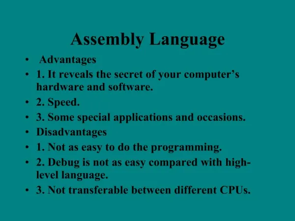
Assembly Language
Assembly Language. CS 6303 Rashad Sierra. What is Assembly Language and why do we need it?. The CPU only understands machine language. Machine language is “a binary language, which means that all machine language instructions are in binary form” (Runnion pg2)

Assembly Language
E N D
Presentation Transcript
Assembly Language CS 6303 Rashad Sierra
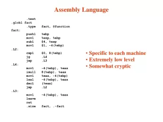
What is Assembly Language and why do we need it? • The CPU only understands machine language. • Machine language is “a binary language, which means that all machine language instructions are in binary form” (Runnion pg2) • “Assembly Language is just a symbolic form of machine language.” (Runnion pg2) • In order to run on the CPU, every program must be converted into machine language. • In essence we are programming within the CPU.
The CPU Design Graphic taken from Art of Assembly by Randall Hyde
Assembler • The Assembler performs the translation from assembly language to machine language. • It is essentially a compiler that lets you address and access memory directly. • It has a defined Instruction set consisting of opcodes and operands. • It gives you access to the processor registers set.
The Registers Set • “The Register set consist of all registers in the CPU that are accessible to the programmer.” (Mano & Kime, pg 484) • A register is the fastest of all temporary storage type because it is a logical circuit that only depends on the clock and input • All the registers are 16 bits long in Intel 8088 processor. • There are eight general-purpose registers, four Segment Registers, and two Control Registers available to the programmer.
General Purpose Registers • The General Registers have three categories • Data Registers (AX,BX,CX,DX) • Pointer Registers (BP,SP) • Index Registers (DI,SI)
Data Registers • AX (Accumulator register)- used for arithmetic operations. • BX (Base register)- used to access an item in data structure. Ex. Element in array • CX (Count register) - used as a counter in loop operations • DX (Data Register) – used as an extension of AX for 32 bit arithmetic • Each 16 bit register can be separated into two 8 bit registers • AH-High order 8 Bits • AL-Low order 8 Bits
Pointer Registers • SP (Stack Pointer)- Its used together with the Stack Segment to calculate the top of the stackSS:SP • BP (Base Pointer)- useful as an auxiliary stack segment pointer.
Index Registers • DI (Destination Index Registers) - used with string instructions. • SI (source Index Register) – it two is used for string instructions and manipulations
Segment Registers • CS (Code Segment)- contains the origin address of the active code segment. Contains Executable instructions. • SS (Stack Segment)- contains the origin address of the active stack segment. Contains dynamic data that is pushed or popped on the stack. • DS (Data Segment)-contains the origin address of the active stack segment. Contains static data • ES (Extra Segment)- contains the origin address of the active extra segment. Extra segment for data segment.
Control Registers • IP (Instruction Pointer) – The offset in the code segment where the next instruction is. CS:IP • Flag Register – a 16 bit register that indicates the current state of the microprocessor. • Overflow Flag- allows overflow or not • Direction Flag- to add or subtract from index registers • Interrupt Flag- allows system interrupts • Trap Flag- allows to trace single-step execution • Sign Flag- signed or unsigned numbers • Zero Flag- tests if operation produces zero • Auxiliary Carry Flag- carry or borrow in arithmetic operations • Parity Flag- parity bit is odd or even • Carry Flag- used to detect overflow
Flag Register Graphic taken from “A guide to Debug” http://mirror.href.com/thestarman/asm/debug/8086REGs.htm#REGS
Instruction categories • Data Transfer Instructions • Stack Instructions • Data Manipulation Instructions • Arithmetic • Logical • Program Control Instructions • Interrupt Instructions
Data Transfer Instructions MOVE INSTRUCTION • MOV <destination>,<source> • MOV AX,0001 EXCHAGE INSTRUCTION • XCHG <destination>,<source> • XCHG AX,DX
Stack Instructions • We cannot directly move or exchange data to the stack because it is not a register. The stack is a block of contiguous memory addresses. • We must push the data on to the stack and pop it off the stack. • PUSH <source> • POP <destination> • We can push the 16 bit Flag register on to the stack by using the following • PUSHF • POPF
Data Manipulation Instructions • Arithmetic Instructions ADDITION • ADD <Destination>,<source> • ADD AX,0001 SUBTRACTION • SUB <Destination>,<source> • SUB AX,0001 MULTIPLICATION • MUL <source> • MUL BL ; Multiply AL=AL*BL notice only low bits • IMUL <source> • IMUL BX ; Integer Multiply AX=AX*BX notice the whole 16 bits DIVISION • DIV <source> • DIV BL ; Divide AL=AL/BL notice only low bits. • IDIV <source> • IDIV BX ; Integer Divide AX=AX/BX notice the whole 16 bits.
Data Manipulation Instructions #2 • Logical Instruction Logical AND • AND <destination>,<source> • AND AL,BL Logical OR • OR <destination>,<source> • OR AL,BL Exclusive OR • XOR <destination>,<source> • XOR AL,BL NEGATE/ 2’S COMPLEMENT • NEG <destination> • NET AL NOT/ 1’S COMPLEMENT • NOT <destination> • NOT AL
Program Control Instructions • JMP <destination> ; Unconditional Jump • CMP <address1>,<address2> ; Compare and set flags • JA <destination> ; Jump if above • JB <destination>; Jump if bellow • JE <destination>; Jump if Equal • JNE <destination>; Jump if not equal • Instructions are used to make logical decisions in a program
Interrupt Instructions • An interrupt is “an external request for service-a request for the processor to stop executing a procedure and to being executing a procedure that has been previously designated to service interrupts of the designated type” (Runnion, pg 374) • We will use Interrupts to get Input/Output (I/O) in the assembly language. • We can use interrupts to write onto a hard disk, read data from the keyboard, and display information to the monitor.
Printing ! to the Screen • MOV AH,02 ; Interrupt instruction to print • MOV DL,24 ; 24 ASCII code for ‘!’ • INT 21 ; Call the Interrupt 21 • MOV AH,4C; Interrupt instruction to return • INT 21; Call INT 21
Reading Char from keyboard until ‘!’ Assume instruction start at memory address 100 • JMP 108 ; Jump to memory location • MOV AH,02 ; Move 02 Print instruction • MOV DL,07 ; Move 07 into DL to beep • INT 21 ; Call Interrupt 21 • MOV AH,01 ; Move 01 Read Char from keyboard • INT 21 ; Call Interrupt 21 • CMP AL,21 ; Compare if Char is ‘!’ • JNZ 102 ; if not print char and read again • MOV AH,4C ; Move 4C to quit safely • INT 21 ; Call Interrupt • NOP ; NO Operation
Debug –Assembly code in action • A small tool called “debug”, which is included in every windows computer, will show the registers and the assembly language instructions.
Works Cited • Runnion, William C. “Structured Programming in Assembly language for the IBM PC” PWS-KENT –Massachusetts 1998 • Mano & Kime, M.Morris & Charles. “Logic and Computer Design Fundamentals” Prentice Hall – New Jersey 2004 • Hyde, Randall. “The Art of Assembly” No Starch Press- California 2003