Download
1 / 57
570 likes | 768 Views
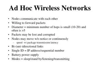
MULTIPLE TREE VIDEO MULTICAST OVER WIRELESS AD HOC NETWORKS Wei Wei and Avideh Zakhor. Presented by Venkat Rajiv Vasireddi Pradeep Ramamoorthy. Video Communication. Why is video communication far more challenging, when compared to data communication? Delay sensitive! Loss sensitive!

E N D
MULTIPLE TREE VIDEO MULTICAST OVER WIRELESS AD HOC NETWORKSWei Wei and AvidehZakhor Presented by Venkat Rajiv Vasireddi PradeepRamamoorthy
Video Communication • Why is video communication far more challenging, when compared to data communication? • Delay sensitive! • Loss sensitive! • What about video communication over wireless ad hoc networks? • Multicast.
Multiple Tree Video Multicast • Basic idea: • Split the video into multiple streams using Multiple Descriptive Coding(MDC). • Send each part over different trees, which are considered to be disjoint. • Multiple Disjoint Trees Multicast Routing Protocol (MDTMR). • Two approaches: • Serial MDTMR. • Parallel MNTMR.
Multiple Description Coding • 3 prediction loops in encoder so the decoder can still track the encoder state when a description is lost. • Use of central predictor and 2 side predictors. • Two descriptions generated by duplicating large DCT Coeff’s in both descriptions and alternating Small one’s between descriptions. • Decoder uses advanced motion compensated temporal interpolation scheme for recovery. • Pairwise correlating transform (PCT) is used to code prediction errors. • Example-Multiple Description Motion Compensation.
Tree Connectivity • Tree connectivity level P: P = E[N]/M where, M: total number of receivers and trees. • Given a random topology with n nodes, one sender and m receivers, N is the sum of all receivers connected to each multicast tree. • E[N] is the expected value of N over all topologies.
Tree Similarity • Measures the level of disjointness of two trees. • More specifically, similarity S between 2 trees is: • The ratio of the number of shared nodes to the number of middle nodes of the tree with a smaller number of middle nodes. • Disjoint trees S = zero. • Identical trees S = one.
Serial MDTMRIntroduction • Based on the On Demand Multicast Routing Protocol (ODMRP). • Construct two node-disjoint trees. • First, build the shortest-path multicast tree. • Next, construct another tree without the middle nodes of the first tree. • How are packets sent?
On Demand Multicast Routing Protocol(ODMRP) • Uses the concept of forwarding groups to forward multicast packets on the shortest path between any member pair – this results in a mesh. • Overcomes the channel overhead and scalability issues of multicast tree based approaches. • Group membership and multicast routes are updated on demand. • Broadcasts Join Requests and Join Tables for mesh construction. • Soft state approach used to maintain multicast group members.
Serial MDTMRTree Construction (Step I) • Source broadcasts a JOIN REQUEST message. • When a node receives this, • it stores the upstream node’s ID and, • rebroadcasts. • When a JOIN REQUEST reaches a receiver, it sends a JOIN ACK to the source, via the reverse shortest path.
Serial MDTMRTree Construction (Step II) • Sender now sends another JOIN REQUEST for the second tree. • Nodes forward only if they’re not a middle node of tree 1. • When the JOIN REQUEST reaches a receiver, it sends a JOIN ACK to the source, via the reverse shortest path in the second tree.
Receiver Sender Receiver
Parallel MNTMRMotivation • Drawbacks of SERIAL MDTMR. • Primary design goals: • Low routing overhead and construction delay. • High tree connectivity. • Low tree similarity. • Distributedness.
In a General Single Tree Model… • Source broadcasts a join-query (JQ) message to its neighbors. • Each node forwards its earliest JQ to its neighbors, and so on, till it reaches the receivers. • Each receiver sends a join-reply (JR) message to the sender to construct the tree.
Parallel MNTMRIntroduction • Aim – construct two nearly disjoint trees in parallel. • Principle – classify nodes randomly into two categories: group 0, or group 1. • However, tree connectivity may be low. • Solution: force every node connected to the sender to forward a JQ message at most once in a JQ process.
PARALLEL MNTMRMessage Classification • Pure JQ Message – A JQ message forwarded by nodes in the same group. • Mixed JQ Message – A JQ message forwarded by nodes in both groups. • Group-iJQ Message – A JQ message whose last hop is a group-i node.
Parallel MNTMRTree Construction (Step I) • When a node receives a JQ message: • It checks if the message satisfies the JQmessage storing condition. • If it does, the message is stored in the node’s JQ message cache. • Else, it is discarded. • Before forwarding the message, the node checks if the message satisfies the JQmessage forwarding condition.
Parallel MNTMRMessage Storing Condition • A JQ message received by node a satisfies the storing condition if: • It is the firstJQ message the node receives in this round. • If it satisfies both these conditions: • Number of hops no larger than that of the first JQ message of node a plus one. • JQ message not forwarded by node a.
Parallel MNTMRMessage Forwarding Condition • A JQ message received at node a satisfies the forwarding condition if: • It has not been forwarded by a. • The last hop was a sender or a group-x node. • If this condition is satisfied, the message is ready to be forwarded.
Parallel MNTMRMessage Forwarding • A group-x node forwards the earliest receivedJQ message of the same group immediately. • If there is no message from the same group, it forwards the earliest received JQ message of the other group, after a delay d. • The JQ message is forwarded till it reaches the receiver.
Parallel MNTMRTree Construction (Step II) • When the receiver gets the JQ messages: • It selects one upstream node for each tree – using the upstream node selection rule. • Sends two JR messages via the selected nodes. • This initiates the tree construction process. • When a node receives a JR message: • It too, selects an upstream node. • Forwards the message via the selected node. • Message eventually reaches the sender.
N Discard JQ Message JQ Message END Y Storing Condition? Forwarding Condition? Store JQ Message in Cache
1st JQ Message? N Store JQ Message in Cache Y Y Forwarding Condition? Forward JQ Message Set JQ-Delay Timer
N END Y 1st JQ Message? Receiver?
1st JQ Message? N Y Set Receiver Timer
Group-y pure JQ and No JR for tree-y Y Select an Upstream Node Unicast a JR Message to Sender for Tree-y END
Parallel MNTMRUpstream Node Selection Rule • Objective – to maximize the disjointness of two trees. • If there exist both group-0 and group-1 messages in the cache, the node selects the earliest received messages from each group as the upstream node for the respective trees. • If only messages from a certain group exist in the cache, the node selects the earliest and second earliest message. • If there is only one element, it is selected as the upstream node for both trees.
Group -0 last hop Tree-0 Node ‘a’ JR from Receiver Group -1 last hop Tree-1 G-1,2 G-0,2 G-1,1 G-0,1 JQ Message Cache
Group -0 ,1 last hop Tree-0 Node ‘a’ JR from Receiver Group -0,2 last hop Tree-1 G-0,4 G-0,3 G-0,2 G-0,1 JQ Message Cache
Group -0 ,1 last hop Tree-0 Node ‘a’ JR from Receiver Group -0,1 last hop Tree-1 G-0,1 JQ Message Cache
Performance Metrics • Ratio of bad frames. • Number of bad periods. • Normalized packet overhead. • Forwarding efficiency. • Average hops of each packet. • Tree similarity.
Simulation Results (III)No. of Control Packets/Frame vs. Max. Speed
Simulation Results (IV)No. of Forwarded Packets/Received Packet vs. Max. Speed
Simulation Results (V)Average Hops of Each Packet vs. Max. Speed
Simulation Results (VI)Ratio of Bad Frames vs. Total Cross Traffic
Simulation Results (VII)No. of Bad Periods vs. Total Cross Traffic
Simulation Results (VIII)Ratio of Bad Frames vs. No. of Receivers
Simulation Results (IX)Ratio of Bad Periods vs. Node Density
Simulation Results (X)No. of Control Packets/Frame vs. Node Density
Simulation Results (XIII)Average No. of Middle Nodes vs. Node Density
What is the Paper Missing? • Assumption: Network is lightly loaded, reasons for packet drop are mobility and poor channel rather than congestion. • Protocol fails when heavily loaded. • Connectivity level has to satisfy • How is node density calculated? • Even with a larger node density, lesser connectivity could happen based on global node placement in the simulation area.
What the Paper is Missing? Contd. • What is the probability that both the MDC packet reach the decoder? • No study of the effect of increasing the number of multipaths and MDC’s . • In parallel MNTMR, the primary requirement is the grouping of nodes. Hard to achieve. • Uses only 8 fps. Not the ideal number for video. • Use of tree structure compared to a mesh structure. • Random way point model is used for simulations. Not the ideal model.
Classification of Mobility and Mobility Models I-Based on Controllability II-Based on Model Construction