Rasterization
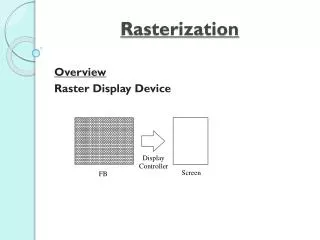
Rasterization. Overview Raster Display Device. Scan Conversion / Rasterization : converting vector graphics into raster graphics (determining pixels in raster graphics to represent primitives in vector graphics). P b (x b ,y b ). P a (x a ,y a ). Scan Converting Lines

Rasterization
E N D
Presentation Transcript
Rasterization Overview Raster Display Device
Scan Conversion / Rasterization: converting vector graphics into raster graphics (determining pixels in raster graphics to represent primitives in vector graphics).
Pb(xb,yb) Pa(xa,ya) • Scan Converting Lines The Basic Incremental Algorithm A line scan-converting algorithm computes the coordinates of the pixels that lie on or near an ideal, infinitely thin straight line imposed on a 2D grid.(Selects pixels on the line to light up.)
We need to compute xa, xa+1, xa+2, …, xb ya, ya+1, ya+2, …, yb dy=yb-ya; dx=xb-xa; m = dy /dx; for i = a, a+1, …, b. Xi,
To increase efficiency, we consider yi= ya+ m*(xi– xa) and xi+1= xi + 1 yi+1= ya+ m*(xi+1- xa) =ya+ m*(xi+1- xa) = ya+ m*(xi – xa) + m = yi+ m …. Since pixels are at integer locations, we need round up if m is not an integer:
Desired line (xi+1,Round(yi+m)) (xi+1, yi+m) (xi, yi) (xi, Round(yi)) • pi(xi, round(yi)), i=a, a+1, a+2, …,b.
DDA (digital differential analyzer): void Line(intxa, intya, intxb, intyb, int color) { int x; float dy, dx, y, m; dy=yb-ya; dx=xb-xa; m=dy/dx; y=ya; for(x=xa; x<=xb; x++) { // light the pixel near (x,y) with the color setPixelColor(x, (int)(y+0.5), color); y += m; } }
This code is only good for |m|<=1. • Swap x and y when calling the function with |m|>1, and a flag is needed for displaying the swapped case. • Drawbacks: accumulating error, FP operation.
Midpoint Line Algorithm Bresenhan Algorithm: Only use integer operation. No accumulation error. • Rule: if midpoint below the line, use upper pixel; if it is above use lower pixel.
dy = yb – ya dx = xb - xa • B = ya– (dy/dx) * xa;
Note b < 0 if dx > 0. • Decision variable for any given point P(xp,yp) is: d(xp,yp)=a xp + b yp + c. • if d=0: P is on the line • if d<0: P is above the line • if d>0: P is below the line
Pb(xb, yb) d(M2) Pp(xp, yp) Pp+1(xp+1, yp+1) M1 Pa(xa, ya) dstart(M1) Recursive Midpoint Algorithm To start the recursion, we need a starting point and the starting decision variable for the next point. We chose Pa(xa, ya) as the starting point and compute dstart.
Give any selected point P(xp, yp), we need decide where is the next point. • Compute the new decision variable for the midpoint. • if d=0: midpoint is on the line pick NE or E • if d<0: midpoint is above the linepick E • if d>0: midpoint is below the linepick NE
An efficient way to compute d for one step further • If E is chosen NE M P(xp, yp) Previous pixel current pixel next pixel
If NE is chosen: NE M E , y Previous Choices for Choices for pixel current pixel next pixel
To compute new d: To make integer operations, we use “2d” instead of d. • Advantages of the Midpoint Algorithm: (1) Additions only. (2) Integer operations only.
void MidpointLine(intxa, intya, intxb, intyb, int color) { int x, y; intdy, dx, incrE, incrNE, d; dx=xb-xa; dy=yb-ya; d=2*dy-dx; incrE=2*dy; incrNE=2*(dy-dx); x=xa; y=ya; SetPixelColor(x, y, color);
while(x<xb) { if(d<=0) /* choose E */ { x++; d+=incrE; } else /* choose NE */ { x++; y++; d+=incrNE; } SetPixelColor(x, y, color); } }
void CirclePoints(int x, int y, int color) { SetPixelColor(x, y, color); SetPixelColor(y, x, color); SetPixelColor(y,-x, color); SetPixelColor(x,-y, color); SetPixelColor(-x,-y, color); SetPixelColor(-y, -x, color); SetPixelColor(-y, x, color); SetPixelColor(-x, y, color); }
Center at origin, if it is not at origin, add shift value • Rule: midpoint inside circle, choose E, outside circle, choose SE. Given point P(x,y), the decision variable is d(x, y)=x2+y2-R2 • if d=0: midpoint is on the circle pick E or SE • if d<0: midpoint is inside the circle pick E • if d>0: midpoint is outside the circle pick SE ->At each step of the iteration: • Choose the pixel based on the sign of d, computed in previous iteration. • Update the decision variable d with corresponding .
value for the next iteration: • dold<0 E • dold>0 SE
Initialization: P(xa=0, ya=R) on the circle • d(xa,ya)=xa2+ya2-R2=0 void MidpointCircle(int R, int color) { int x, y, d; x=0; y=R; d=1-R CirclePoint(x, y, color); while(y>x) { if(d<0) /* choose E */ { d+=2*x+3; x++; }
else { d+=(x-y)*2+5; x++; y--; } CirclePoint(x, y, color); } }
Fill Rectangles -> Area Fill • Choosing pixels inside the area • setPixelColor(x, y, color) We may need to compute color based on x, y if the filling is not a single color. A simple rectangle single color filling algorithm: int x, y for (y=ymin; y<=ymax; y++) /* for each scan line */ for (x=xmin; x<=xmax; x++) /* for each pixel */ setPixelColor(x, y, color);
Rules for shared edges =>A shared vertical edge belongs to the rightmost of the two sharing shapes =>A shared non-vertical edge belongs to the upper shape. =>Therefore only draw the pixels on the left and bottom edges. • Revised code for rectangle single color filling: • int x, y • for (y=ymin; y<ymax; y++) • for (x=xmin; x<xmax; x++) • SetPixelColor(x, y, color);
FillPolygons (Polygon Scan-Conversion) • Parity: number of times a scan line has intersected the polygon. Initially it is 0 (even). • Extrema: the intersection points of the scan line with the polygon. • Span: a segment of a scan line between two consecutive extrema that is also within the polygon.
The Odd-Parity Rule =>For each intersection encountered, inverts the parity. =>Draw when the parity is odd. =>Don’t draw when it is even. The span-filling algorithm for filling a polygon on a scan-line: ->Find the intersections of the scan line with all edges of the polygon (extrema for the spans) ->Sort the intersections by increasing x coordinate ->Fill in all pixels between pairs of intersections that lie interior to the polygon (span), using the odd-parity rule to determine a point is inside the polygon or not. Polygon Filling Rule: draw only pixels that lie interior or on a left or bottom edge.
Four elaboration on handling intersection points: =>Fraction intersection x values: Round down x coordinate if the parity is even (when this intersection is counted); round up x coordinates if the parity is odd (when this intersection is counted). Count the pixel that are exactly inside. =>Integer intersection x values: Left (odd) in. Right (even) out. =>Shared vertices: Count ymin, don’t count ymax. =>Horizontal edges: Draw the bottom ones. Ignore horizontal edges when computing intersection points.
PSC (Polygon Scan Conversion): determine the pixels and set them to the specified color. =>Algorithm: Find the first and the last scan line that intersect with the polygon. first: y=ymin: (min y value of the polygon) last: y=ymax: (max y value of the polygon) For each scan line between [ymin, ymax], fill the spans (span-filling) : Three stages of span filling: -> Find (the extrema by intersecting the scan line with the polygon). -> Sort (the extrema by x) -> Fill (the pixels using the odd-parity rule).
• Implementation • Edge Coherence: many edges intersected by scan line i also intersected by scan line i + 1. • AET: Active Edge Table, a linked list of extrema sorted by their x values for the current scan line. • ET: Edge Table (an array of pointers to the linked lists of newly intersected edges by each scan line).
10 9 8 7 DE EF 6 9 7 -5/2 10 7 7/3 5 CD 4 10 14 0 3 FA 2 9 2 0 1 AB BC 0 3 7 -5/21/m 5 7 3/2
AET pointer AB BC 3 7 -5/2 5 7 3/2 ymax x 1/m AET for scan line y = 1
AET pointer AET pointer AB FA BC BC 3 9 9/2 2 0 -5/2 5 5 17/2 10 3/2 3/2 ymax ymax x x 1/m 1/m AET for scan line y = 2 … AET for scan line y = 3
AET pointer FA CD DE EF 9 2 0 9 2 -5/2 10 10 7/3 10 14 0 AET pointer • Build the ET. • Initialize AET=0. AET for scan lines y = 10
for (y= ymin; y<=ymax; y++) { ->Remove entries at AET whose ymax is smaller or equal to y. (ymax out). ->Add ET entry for this scan line into the AET. ->Compute the intersection point (extrema) x for each of the entries in the AET. ->Sort the entries by x. ->For each pair of extrema, fill the pixels in between. for (x=x1; x<x2; x++) SetPixelColor(x,y); }
Slivers: relax the filling rule, count nearby pixels Texture Filling
Pattern Filling setPixelColor(x,y,pattern[x%M,y%N]);
Clipping in a Raster World Clipping cuts the outside parts out before displaying • Clipping a point. • Point P(x, y) • if ((x>=xmin && x<=xmax) && (y>=ymin && y<=ymax)) • setPixelColor(x, y, color);
Clipping filled polygons • =>Clip while scan-convert. • =>Clip extrema in pairs: • . Keep the pair if both extrema are inside. • . Remove the pair if both extrema are outside and on the same side. • . Move the outside extreme point to the edge if one extreme point is out • and the other is in.
Clip Lines Basic Procedure: • Trivial acceptance: both end-points are inside. • Intersect the line with the edges of the clipping polygon and use the intersection points as the new end-points for the line. (x2,y2) 1 2 (xi,yi) 1 (x1,y1) 2
How to find the intersection point of the line with an edge. e.g. left edge: x=xmin, ymin<=y<=ymax 3) line equation 0<=t<=1 • intersection point: (xi, yi), ti • 1) xi=xmin Four edge equations: left: x=xmin, ymin<=y<=ymax • right: x=xmax, ymin<=y<=ymax • top: y=ymax, xmin<=x<=xmax • Bottom:y=ymin,xmin<=x<=xmax 2) xi=x1+ti(x2-x1) • For any line, we need to make sure: • 0<=ti<=1; • ymin<=yi<=ymax; xmin<=xi<=xmax • For vertical line: x1=x2, we need to • make sure: xmin<=x1<=xmax
For a line with ending points: p1 and p2(0)Find the outcodes for p1 and p2(1) Trivial acceptance: both outcodes equal to 0.(2) Trivial rejection: if ((outcode1 & outcode2)!=0).(3) Non-trivial cases: for each ending point, we clip to the top, bottom, right, left edges in the order as needed, until the clipped line can be trivially accepted or rejected. The Cohen-Sutherland Line Clipping Four bit out codes for the ending points:
Parametric Line-Clipping Algorithm • Cohen-Sutherland: computes x and y for every intersection points (including the intermediate ones). • Parametric: computes t first, only computes x and y for the clipped ending points. • Parametric Clipping Cyrus-Beck, Liang-Barsky • Basics: (1)Find intersection points between the line and the edges. Compute four t values (can be 0< or >1). (2)Determine which pair of t’s to use to define the line segment that is inside.
Mathematics • V1V2>0 <900 • V1V2=0 =900 • V1V2<0 >900 • The inside half-plane of an edge is the one containing the clipping rectangle • Counter clockwise rule: Enumerate the edges counter clockwise • inside half-plain is always to the left of a directed edge • The (outward) normal of an edge is pointing to the outside half-plane and perpendicular to the edge. (normal is an unit vector). • Computing t at an intersection point.
D= P0P1 = P1-P0 P(t) = P0 + t D • For any point Ei on the edge: PEiP=P-PEi • (NiPEiP)>0 <900 Point outside • (NiPEiP)=0 =900 Point on the edge • (NiPEiP)<0 >900 Point inside
Ni[P(t)-PEi]=0 • Ni[P0+tD-PEi]=0 • Ni[P0-PEi] + t NiD = 0 • Taking care of NiD=0 • The line is parallel to the edge. D is parallel to the edge • D=0P0=P1
Cyrus-Beck Parametric Line Clipping • Intersections are potentially entering the clipping • rectangle(PE) if NiD<0; >900. 2 PEs • Intersections are potentially leaving(PL) if NiD>0; <900. 2 PLs • The inside line segment PEPL • -> largest tE, smallest tL • -> tE<=tL • -> tE>0; tL<=1 • Special case: NiD=0 • ->Check x value for vertical line and y value for horizontal lines
Cyrus-Beck Algorithm • { • precalculate Ni and select a PEi (i=0, 1, 2, 3) for each edge • for (each line to be clipped) • { • if(P1==P0) Point clip • else • { • tE=0; tL=1 • for (each edge) • { • if(NiD==0) clip vertical / horizontal line • else • if(PE, NiD<0) tE=max(tE, t) • if(PL, NiD>0) tL=min(tL, t) • } • } • if(tE > tL) no display • else display with tE and tL • } • } • }
Polygon clipping (lines) • Sutherland-Hodgeman Algorithm • for(each edge of the clipping rectangle) • { • if the vertex is in the inside half plane • add to the list • else don’t add • add all intersection points with 0<= t <=1 • } • display list