Understanding Transport Layer: Process-to-Process Delivery in TCP and UDP
Explore the role of the transport layer, process-to-process delivery, congestion control, and more through TCP and UDP protocols. Learn about port numbers, multiplexing, sliding windows, and sequence numbers.

Understanding Transport Layer: Process-to-Process Delivery in TCP and UDP
E N D
Presentation Transcript
PART V Transport Layer
Chapters Chapter 22 Process-to-Process Delivery Chapter 23 Congestion Control and QoS
Chapter 22 Process-to-ProcessDelivery:UDP and TCP
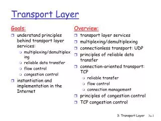
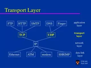
22.1 Process-to-Process Delivery Client-Server Paradigm Addressing Multiplexing and Demultiplexing Connectionless/Connection-Oriented Reliable/Unreliable
Note: The transport layer is responsible for process-to-process delivery.
22.2 UDP Port Numbers User Datagram Applications
Note: UDP is a connectionless, unreliable protocol that has no flow and error control. It uses port numbers to multiplex data from the application layer.
Note: The calculation of checksum and its inclusion in the user datagram are optional.
Note: UDP is a convenient transport-layer protocol for applications that provide flow and error control. It is also used by multimedia applications.
22.3 TCP Port Numbers Services Sequence Numbers Segments Connection Transition Diagram Flow and Error Control Silly Window Syndrome
Example 1 Imagine a TCP connection is transferring a file of 6000 bytes. The first byte is numbered 10010. What are the sequence numbers for each segment if data are sent in five segments with the first four segments carrying 1000 bytes and the last segment carrying 2000 bytes? Solution The following shows the sequence number for each segment: Segment 1==> sequence number: 10,010 (range: 10,010 to 11,009) Segment 2 ==> sequence number: 11,010 (range: 11,010 to 12,009) Segment 3==> sequence number: 12,010 (range: 12,010 to 13,009) Segment 4 ==> sequence number: 13,010 (range: 13,010 to 14,009) Segment 5 ==> sequence number: 14,010 (range: 14,010 to 16,009)
Note: The bytes of data being transferred in each connection are numbered by TCP. The numbering starts with a randomly generated number.
Note: The value of the sequence number field in a segment defines the number of the first data byte contained in that segment.
Note: The value of the acknowledgment field in a segment defines the number of the next byte a party expects to receive. The acknowledgment number is cumulative.
Note: A sliding window is used to make transmission more efficient as well as to control the flow of data so that the destination does not become overwhelmed with data. TCP’s sliding windows are byte-oriented.
Note: In TCP, the sender window size is totally controlled by the receiver window value (the number of empty locations in the receiver buffer). However, the actual window size can be smaller if there is congestion in the network.
Note: Some points about TCP’s sliding windows: The source does not have to send a full window’s worth of data. The size of the window can be increased or decreased by the destination. The destination can send an acknowledgment at any time.