A Sparse Undersea Sensor Network Decision Support System
Defense and Security Symposium 2007. A Sparse Undersea Sensor Network Decision Support System Based on Spatial and Temporal Random Field. Dr. Bo Ling Migma Systems, Inc. Dr. Mike Traweek Office of Naval Research Dr. Tom Wettergren Naval Undersea Warfare Center. April 10, 2007.

A Sparse Undersea Sensor Network Decision Support System
E N D
Presentation Transcript
Defense and Security Symposium 2007 A Sparse Undersea Sensor Network Decision Support System Based on Spatial and Temporal Random Field Dr. Bo Ling Migma Systems, Inc. Dr. Mike Traweek Office of Naval Research Dr. Tom Wettergren Naval Undersea Warfare Center April 10, 2007
Presentation Outline - Problem Statement - Random Field Estimation of Undersea Sensor Network - Forward & Backward Mapping Mitigation - Spatial & Temporal Layering Discrimination - A Simulation Tool for Target Detection and Tracking - Conclusion
Problem Statement No Overlapping In a passive submarine detection system, we need to consider: - Number of sensors required in the sparse sensor network - Probability of submarine detection when a submarine might be detected by only one sensor at one particular time instance - False alarm mitigation A Large Surveillance Region
Problem in Motion Based Detection In a sparse sensor network, targets can be detected and tracked over a period of time. As a target moves, although it may not be detected by any sensors at certain time instance, it will be detected by a number of sensors over a period of time. When positive and negative reports co-exist, it is difficult to determine if targets actually exist!
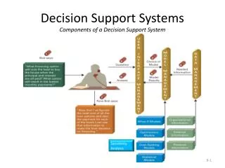
Basic System Architecture Although targets in a surveillance region may not always be detected, as they move, sensors can collectively detect, classify and track them.
Random Field for Undersea Sensor Network A typical random field model can be described by the following difference equation:
Random Field Estimation In random field modeling setting, it is always assumed that Z = {Zij | (i, j) } is stationary and Gaussian distributed with known or empirical mean and variance. Gaussian Random Field (GRF) or Gaussian-Markov Random Field (RMRF) modeling has been widely used in image processing. In undersea sensor network, the assumption of stationary process and Gaussian or Markov distribution needs to be carefully verified.
Our Approach for Random Field Estimation Based on the continuation of sensor outputs, the random field zf over two consecutive samples must be similar provided that the sampling rate is large enough or the sampling time is small enough. Mathematically, suppose and are the random fields at the sampling time instants k and k+1. Then, based on the continuation property, the quantity of || - || is small. Minimize:
FBMM Technology (Patented) Forward & Backward Mapping Mitigation It can be used to reduce false reports while keeping the positive reports.
A Simulated Network 2020 sq. miles Detections after 2 hours Two targets at 180 m/h Both true and false detections co-exist 200 sensors
Difficult to Find Targets Visually What an operator will see after two-hour monitoring. Are there any targets?
Random Field Estimation Random field estimated using our LMI-based optimization
Mathematical Morphological Operation Morphological operators can be applied to reduce false detections
Backward Mapping Backward Mapping for refined situation awareness.
STLD Technology (Patented) Spatial & Temporal Layering Discrimination STLD technology applies temporal patterns to further reduce the false reports.
Gap Statistics Based Clustering Gap Statistic (Robert Tibshirani, Guenther Walther, Trevor Hastie, “Estimating the number of clusters in a data set via the gap statistic”, J. R. Statist. Soc. B (2001), 63, Part 2, pp. 411-423) is a technique used to estimate the number of clusters in the data.
Temporal & Spatial Mitigation Detections in each cluster are checked for both temporal and spatial patterns. Temporal Pattern - True detections must show temporal trend Spatial Pattern - True detections must be relatively close spatially
False Reports Reduction Using STLD After FBMM Processing After STLD Processing
Combine FBMM & STLD FBMM STLD
Target Synthetic Tracks Groundtruth Synthetic Tracks
Conclusion - In a sparse undersea network, targets can be detected and tracked based their motion - The mixture of both positive and negative reports makes it difficult for an operator to determine whether or not targets are actually present - Our patented Forward & Backward Mapping Mitigation technology and Spatial & Temporal Layering Discrimination technology can help operator make better decisions