Download
1 / 25
250 likes | 366 Views
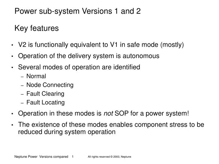
Power sub-system Versions 1 and 2 Key features. V2 is functionally equivalent to V1 in safe mode (mostly) Operation of the delivery system is autonomous Several modes of operation are identified Normal Node Connecting Fault Clearing Fault Locating

E N D
Power sub-system Versions 1 and 2 Key features • V2 is functionally equivalent to V1 in safe mode (mostly) • Operation of the delivery system is autonomous • Several modes of operation are identified • Normal • Node Connecting • Fault Clearing • Fault Locating • Operation in these modes is not SOP for a power system! • The existence of these modes enables component stress to be reduced during system operation
Version 2 physical location options • Power sub unit can be in the BU or Node 10A circuit 10A circuit 10A circuit 10A circuit BU BU Science Node Pressure-Cases 1A circuit 1A circuit
Concept of operations • Design continues to be refined • Simple reliable operation is key • Voltage is used as a signal to the autonomous BU control
Concept of operations * These mean current-limit operation at the shore station Appropriate sequencing gives unambiguous operation
Initial switch state is unknown Shore station is in current limit operation Regardless of whether a fault is present Positive voltage is sensed Backbone breaker is closed Science node connection is opened If there is a fault, its location is measured from shore Return to unpowered state after fault location determined Concept of operations Fault Locating Mode, + 500 V +500V Un-powered
Initial BB switch state is closed Shore station is in current-limit operation If a fault is present Time-coordinated protection begins when current becomes non-zero Unit closest to fault trips first If no fault is present Backbone breakers remain closed In either case, status is stored Concept of operations Fault Clearing Mode, -500V -500V Un-powered
Initial science node switch state is open Shore station is constant voltage operation Spur cable resistance is measured at low current If no fault detected, spur switch closes If fault detected, spur switch stays open In either case, status is stored Concept of operations Science Connecting Mode, -1000 V - 500V -1000V
The control knows what the switch status is The control knows that is is in the Normal Mode If a fault occurs during Normal Mode operation No switch action results Shore station enters current limit mode Concept of operations Normal Mode, -6000 V to – 10,000 V -1000V -10kV
Shore station shuts the system down There is no change in the state of any switch The location of faults, if any, is not known to the shore station If the shutdown is not because of a fault, the fault location step can be omitted Concept of operations Controlled shutdown from normal mode Un-powered -10kV
Circuit description • Simplified circuit, un-powered 0V Control Control To Science
Circuit description • Fault Location mode • Power Feed output to +500V +500V Control Control To Science
Circuit description • Fault Location mode • Start up supply charges +500V Control Control To Science
Circuit description • Fault Location mode • Next cable section connected +500V Control Control To Science
Circuit description • Fault Location mode • Second start up supply charges +500V Control Control To Science
Circuit description • Fault Location mode • Second relay closes +500V Control Control To Science
Circuit description • Fault Location mode • Zeners power control if fault I +500V Control Control
At the end of Fault Locating sequence: • All backbone breakers are closed (onto fault, if there is one) • All spur cable switches are open • Next part of sequence is Fault Clearing
Circuit description • Fault Clearing mode • Supply to – 500 V, current limited -500V Control Control To Science
Circuit description • Fault Clearing mode • Backbone switches open if appropriate -500V Control Control To Science
At the end of Fault Clearing sequence: • Nearly all backbone breakers are closed • If there is a fault, closest breakers are open • All spur cable switches are open • Next part of sequence is Science Node Connecting
Circuit description • Science Connecting mode • Power feed output increased to -1000V -1000V Control Control To Science
Circuit description • Science Connecting mode • Spur Cable switches closed if not faulted -1000V Control Control To Science
At the end of Science Connecting sequence: • Nearly all backbone breakers are closed • If there is a fault, closest breakers are open • All spur cable switches are closed (unless faulted) • Next part of sequence is Normal Operation
Circuit description • Power feed output increased to 10kV, system fully powered -10kV Control Control To Science