Download
1 / 58
590 likes | 801 Views
Pertemuan 15 Organisasi I/O: I. Matakuliah : T0324 / Arsitektur dan Organisasi Komputer Tahun : 2005 Versi : 1. Learning Outcomes. Pada akhir pertemuan ini, diharapkan mahasiswa akan mampu :

E N D
Pertemuan 15Organisasi I/O: I Matakuliah : T0324 / Arsitektur dan Organisasi Komputer Tahun : 2005 Versi : 1
Learning Outcomes Pada akhir pertemuan ini, diharapkan mahasiswa akan mampu : • Mahasiswa dapat membandingkan beberapa metode pengaksesan peralatan I/O dalam sistem komputer ( C4 ) ( No TIK : 7 )
Chapter 4. Input/Output Organization: I
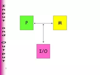
Processor Memory Bus I/O de vice 1 I/O de vice n Figure 4.1. A single-bus structure.
Mo v e #LINE,R0 Initialize memory p oin ter. W AITK T estBit #0,ST A TUS T est SIN. Branc h=0 W AITK W ait for c haracter to b e en tered. Mo v e D A T AIN,R1 Read c haracter. W AITD T estBit #1,ST A TUS T est SOUT. Branc h=0 W AITD W ait for displa y to b ecome ready . Mo v e R1,D A T A OUT Send c haracter to displa y . Mo v e R1,(R0)+ Store c haracter and adv ance p oin ter. Compare #$0D,R1 Chec k if Carriage Return. Branc h 0 W AITK If not, get another c haracter. Mo v e #$0A,D A T A OUT Otherwise, send Line F eed. Call PR OCESS Call a subroutine to pro cess the input line. Figure 4.4 A program that reads one line from the keyboard stores it in memory buffer, and echoes it back to the display.
V dd Processor R I N T R INTR INTR1 INTR2 INTR n Figure 4.6. An equivalent circuit for an open-drain bus used to implement a common interrupt-request line.
Figure 4.7. Implementation of interrupt priority using individual interrupt-request and acknowledge lines.
Main Program Mo v e #LINE,PNTR Initialize buffer p oin ter. Clear EOL Clear end-of-line indicator. BitSet #2,CONTR OL Enable k eyb oard in terrupts. BitSet #9,PS Set in terrupt-enable bit in the PS. . . . In terrupt-service routine – READ Mo v eMultiple R0-R1, (SP) Sa v e registers R0 and R1 on stac k. Mo v e PNTR,R0 Load address p oin ter. Mo v eByte D A T AIN,R1 Get input c haracter and Mo v eByte R1,(R0)+ store it in memory . Mo v e R0,PNTR Up date p oin ter. CompareByte #$0D,R1 Chec k if Carriage Return. 0 Branc h R TRN Mo v e #1,EOL Indicate end of line. BitClear #2,CONTR OL Disable k eyb oard in terrupts. R TRN Mo v eMultiple (SP)+,R0-R1 Restore registers R0 and R1. Return-from-in terrupt Figure 4.9. Using interrupts to read a line of characters from a keyboard via the registers in Figure 4.3.
OSINIT Set in terrupt v ectors: Time-slice clo c k SCHEDULER Soft w are in terrupt OSSER VICES Keyb oard in terrupts IOData . . . OSSER VICES Examine stac k to determine requested op eration. Call appropriate routine. SCHEDULER Sa v e program state. Select a runnable pro cess. Restore sa v ed con text of new pro cess. Push new v alues for PS and PC on stac k. Return from in terrupt. (a) OS initialization, services, and scheduler IOINIT Set pro cess status to Blo c k ed. Initialize memory buffer address p oin ter and coun ter. Call device driv er to initialize device and enable in terrupts in the device in terface. Return from subroutine. IOD A T A P oll devices to determine source of in terrupt. Call appropriate driv er. If END = 1, then set pro cess status to Runnable. Return from in terrupt. (b) I/O routines KBDINIT Enable in terrupts. Return from subroutine. KBDD A T A Chec k device status. If ready , then transfer c haracter. If c haracter = CR, then { set END = 1; Disable in terrupts } else set END = 0. Return from subroutine. (c) Keyboard driver Figure 4.10. A few operating system routines.
Main program MO V R0,#0 STR R0,EOL Clear EOL flag. ADR R1,D A T AIN Load address of Register D A T AIN. contents of CONTROL register. LDRB R0,[R1,#3] Get ORR R0,R0,#4 Set bit KEN in register CONTR OL STRB R0,[R1,#3] to enable k eyb oard in terrupts. MO V R0,#&50 Enable IR Q in terrupts in pro cessor MSR CPSR,R0 and switc h to user mo de. . . . IR In terrupt-service routine Q READ STMFD R13!, { R0 R2,R14 irq } Sa v e R0, R1, and R14 irq on the stack. register ADR R1,DATAIN Load address of D A T AIN. LDRB R0,[R1] Get input character. LDR R2,PNTR Load pointer v alue. STRB R0,[R2],#1 Store character and increment pointer. STR R2,PNTR Up date p oin ter v alue in the memory . CMPB R0,#&0D Chec k if Carriage Return. LDMNEFD R13!, { R0 R2,R14 irq } If not, restore registers SUBNES PC,R14 irq,#4 and return. LDRB Otherwise get CONTROL register. R0,[R1,#3] AND R0,R0,#&FB Clear bit KEN STRB R0,[R1,#3] to disable k eyb oard in terrupts. MO V R0,#1 Set EOL flag. STR R0,EOL LDMFD R13!, { R0-R2,R14 } Restore registers SUBS PC,R14 irq,#4 and return. Figure 4.13. An ARM interrupt-service routine to read an input line from a keyboard based on Figure 4.9.
Main program MO VE.L #LINE,PNTR Initialize buffer p oin ter. CLR EOL Clear end-of-line indicator. ORI.B #4,CONTR OL Set bit KEN. MO VE #$100,SR Set pro cessor priorit y to 1. . . . In terrupt-service routine – READ MO VEM.L A0/D0, (A7) Sa v e registers A0, D0 on stac k. MO VEA.L PNTR,A0 Load address p oin ter. MO VE.B D A T AIN,D0 Get input c haracter. MO VE.B D0,(A0)+ Store it in memory buffer. MO VE.L A0,PNTR Up date p oin ter. CMPI.B #$0D,D0 Chec k if Carriage Return. BNE R TRN MO VE #1,EOL Indicate end of line. ANDI.B #$FB,CONTR OL Clear bit KEN. R TRN MO VEM.L (A7)+,A0/D0 Restore registers D0, A0. R TE Figure 4.15. A 68000 interrupt-service routine to read an input line from a keyboard based on Figure 4.9.
Main program MO V EOL,0 MO V BL,4 OR CONTR OL,BL Set KEN to enable k eyb oard in terrupts. STI Set in terrupt flag in pro cessor register. . . . In terrupt-service routine READ PUSH EAX Sa v e register EAX on stac k. PUSH EBX Sa v e register EBX on stac k. MO V EAX,PNTR Load address p oin ter. MO V BL,D A T AIN Get input c haracter. MO V [EAX],BL Store c haracter. INC D W ORD PTR [EAX] Incremen t PNTR. CMP BL,0DH Chec k if c haracter is CR. JNE R TRN MO V BL,4 X OR CONTR OL,BL Clear bit KEN. MO V EOL,1 Set EOL flag. R TRN POP EBX Restore register EBX. POP EAX Restore register EAX. IRET Figure 4.17. An interrupt-servicing routine to read one line from a keyboard using interrupts on IA-32 processors.
Figure 4.21. Sequence of signals during transfer of bus mastership for the devices in Figure 4.20.
Pertemuan 16Organisasi I/O: II Matakuliah : T0324 / Arsitektur dan Organisasi Komputer Tahun : 2005 Versi : 1
Learning Outcomes Pada akhir pertemuan ini, diharapkan mahasiswa akan mampu : • Membandingkan beberapa metode pengaksesan peralatan I/O dalam sistem komputer ( C4 ) ( No TIK : 7 )
Chapter 4. Input/Output Organization: II
Bus D7 P A7 D A T AIN D1 D0 P A0 SIN Input CA status PB7 D A T A OUT PB0 SOUT CB1 Handshak e control CB2 Sla v e- 1 Ready Master - Ready R / W A31 My-address Address decoder A2 RS1 A1 RS0 A0 Figure 4.33. Combined input/output interface circuit.
D A T A OUT D7 D Q 7 7 Printer data D0 D Q 1 1 D0 D Q 0 0 SOUT Idle Handshak e control V alid Read Load status data R/ W Sla v e- ready Go A31 My-address T iming Address Logic decoder A1 A0 Clock My-address Respond Idle Go=1 Figure 4.35. A parallel point interface for the bus of Figure 4.25, with a state-diagram for the timing logic.
T ime 1 2 3 Clock Address R/ W Data Go Sla v e-ready Figure 4.36. T iming for the output interf ace in Figure 4.35.
Main Processor memory Processor b us Bridge PCI b us Additional SCSI Ethernet USB ISA memory controller interf ace controller interf ace SCSI b us IDE disk V ideo Disk CD-R OM controller controller CD- Disk 1 Disk 2 K e yboard Game R OM Figure 4.38. An example of a computer system using different interface standards.
T ar gets e xamine ID D B 2 D B 5 D B 6 B S Y S E L Free Arbitration Selection Figure 4.42. Arbitration and selection on the SCSI bus. Device 6 wins arbitration and selects device2.
Host computer Root hub Hub Hub I/O I/O I/O I/O Hub de vice de vice de vice de vice I/O I/O de vice de vice Figure 4.43. Universal Serial Bus tree structure.
Host computer Root Hub HS HS Hub A Hub B F/LS HS HS - High speed F/LS - Full/Lo w speed De vice De vice C D Figure 4.44. Split bus operation