Chapter 12
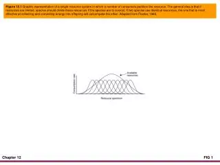
Power Amplifiers. Chapter 12. Classes of operation. Class A means that the transistor collector current flows for 360 o of the ac cycle. Class B amplifiers have collector current for 180 o of the ac cycle. Class C means that current flows for less than 180 o of the ac cycle.

Chapter 12
E N D
Presentation Transcript
Power Amplifiers Chapter 12
Classes of operation • Class A means that the transistor collector current flows for 360o of the ac cycle. • Class B amplifiers have collector current for 180o of the ac cycle. • Class C means that current flows for less than 180o of the ac cycle. • Class D amplifiers switch on and off and spend no time in the linear mode.
IC IC A B t t IC IC ISAT C D t t
Types of coupling • Direct (dc amplifier) • Capacitive (ac amplifier) • Untuned transformer (ac amplifier) • Tuned transformer (narrowband ac amplifier)
dc ac Capacitive Direct ac ac Tuned transformer Transformer
vout This amplifier has two load lines. +VCC RC R1 RL vin R2 RE
100 mA 80 mA 60 mA 40 mA 20 mA 0 mA VCC VCE(cutoff) = VCC The dc load line IC(sat) = RC + RE 14 12 10 IC in mA 8 6 Q 4 2 6 16 2 4 10 12 0 14 18 8 VCE in Volts The ac load line has a higher slope.
Large Signals • When the Q point is at the center of the dc load line, the signal cannot use all of the ac load line without clipping. • MPP < VCC (max. peak-to-peak output) • MPP = 2MP • MP = ICQrcor VCEQ (whichever is smaller)
100 mA 80 mA 60 mA 40 mA 20 mA 0 mA vpp2 MPP2 pout = pout(max) = 8RL 8RL 14 12 10 IC in mA 8 Q 6 4 2 6 16 2 4 10 12 0 14 18 8 VCE in Volts
Efficiency • The dc power supplied to an amplifier is Pdc = VCCIdc • Efficiency = h = pout/Pdc x 100% • The maximum efficiency for Class A amplifiers with a dc collector resistance and a separate load resistance is 25%. • Class A is usually not acceptable when watts of power are required.
Push-pull Class B amplifier Q1 T2 T1 +VCC vin Q2 On the positive half-cycle of the input, Q1 is on.
Q1 T2 T1 +VCC vin Q2 On the negative half-cycle of the input, Q2 is on.
Class B operation • Each transistor conducts for half a cycle. • There is no bias so each transistor is at cutoff with no input signal. • The maximum efficiency is 78.5 percent. • Transformers are bulky and expensive. • The transformers can be eliminated.
1 fr = 2p LC A Class C amplifier Amax +VCC C L f fr RL RB vin
VCC rc Q Class C amplifier dc and ac load lines dc load line IC VCE VCC
+ VP 0 0 -2 VP - VP Negative clamping at the base causes the collector current to flow in brief pulses. IC +VCC C L t RL RB
Class C formulas • BW = f2 - f1 = fr/Q • QL = XL/RS (inductor only) • RP = QLXL (equiv. parallel resistance) • rc = RP RL (ac resistance) • Q = rc/XL (overall circuit) • PD = MPP2/40rc
W T f 360o Duty cycle and conduction angle = D = f = 180o f = 90o
h 100% f f f 180o 180o 180o MPP2 40rc PD The effects of conduction angle in a Class C amplifier Idc
Derating factor • Power devices generate heat • PD(max) rating good up to 25 oC • Decrease in rating = DP • Derating factor = D (W/oC) • TA = ambient temperature (oC) DP = D(TA - 25 oC) • PD(safe) = PD(max) - DP