
Electrical Circuits: Understanding Current, Resistance, and Power in DC Circuits**
E N D
Presentation Transcript
PHY-2049 Chapter 27 Circuits
A closed circuit Hot, Hot Hot
copper 12 volts 0 volts #24 chapter 26: The figure below gives the electrical potential V(x) along a copper wire carrying a uniform current, from a point at higher potential (x=0m) to a point at a lower potential (x=3m). The wire has a radius of 2.45 mm. What is the current in the wire? What does the graph tell us?? *The length of the wire is 3 meters. *The potential difference across the wire is 12 m volts. *The wire is uniform. Let’s get rid of the mm radius and convert it to area in square meters: A=pr2 = 3.14159 x 2.452 x 10-6 m2 or A=1.9 x 10⁻⁵ m 2 Material is Copper so resistivity is (from table) = 1.69 x 10⁻⁸ ohm meters
R1 R2 V1 V2 V i i Series Combinations SERIES Resistors
The rod in the figure is made of two materials. The figure is not drawn to scale. Each conductor has a square cross section 3.00 mm on a side. The first material has a resistivity of 4.00 × 10⁻³ Ω · m and is 25.0 cm long, while the second material has a resistivity of 6.00 × 10⁻³ Ω · m and is 40.0 cm long. What is the resistance between the ends of the rod?
R1, I1 R2, I2 V Parallel Combination??
What’s This??? #26 chapter 27:In Figure below, find the equivalent resistance between points (a) F and H and [2.5](b) F and G. [3.13] ?
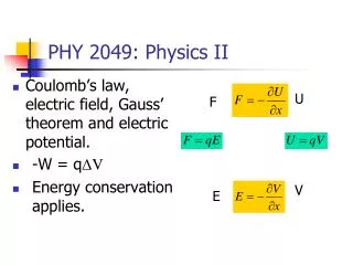
Power Source in a Circuit The ideal battery does work on charges moving them (inside) from a lower potential to one that is V higher.
V By the way …. this is called a circuit! A REAL Power Sourceis NOT an ideal battery Internal Resistance εorEmf is an idealized device that does an amount of work to move a unit charge from one side to another.
A Physical (Real) Battery Internal Resistance
Represents a charge in space Back to Potential Change in potential as one circuits this complete circuit is ZERO!
Consider a “circuit”. This trip around the circuit is the same as a path through space. THE CHANGE IN POTENTIAL FROM “a” AROUND THE CIRCUIT AND BACK TO “a” is ZERO!!
To remember • In a real circuit, we can neglect the resistance of the wires compared to the resistors. • We can therefore consider a wire in a circuit to be an equipotential – the change in potential over its length is slight compared to that in a resistor • A resistor allows current to flow from a high potential to a lower potential. • The energy needed to do this is supplied by the battery.
LOOP EQUATION • The sum of the voltage drops (or rises) as one completely travels through a circuit loop is zero. • Sometimes known as Kirchoff’s loop equation. • NODE EQUATION • The sum of the currents entering (or leaving) a node in a circuit is ZERO
Take a trip around this circuit. Consider voltage DROPS: ε-ir -iR = 0 or ε=ir + iR
Circuit Reduction i=ε/Req
Multiple Batteries Watch the DIRECTION !!
Reduction Computes i
PARALLEL Another Reduction Example
START by assuming a DIRECTION for each Current Let’s write the equations.
Initially, no current through the circuit Close switch at (a) and current begins to flow until the capacitor is fully charged. If capacitor is charged and switch is switched to (b) discharge will follow. RC Circuit How Fast ?
This is a differential equation. • To solve we need what is called a particular solution as well as a general solution. • We often do this by creative “guessing” and then matching the guess to reality.
Discharging a Capacitor qinitial=Cε BIG SURPRISE! (Q=CV) i iR+q/C=0