Download
1 / 20
200 likes | 338 Views
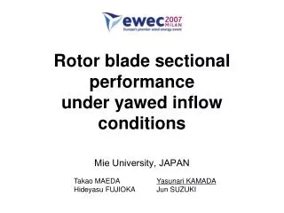
Rotor blade sectional performance under yawed inflow conditions. Mie University, JAPAN. Takao MAEDA Hideyasu FUJIOKA. Yasunari KAMADA Jun SUZUKI. Introduction. Global warming issue. Renewable energy is remarked Wind energy is one of this. Wind turbine.

E N D
Rotor blade sectional performance under yawed inflow conditions Mie University, JAPAN Takao MAEDA Hideyasu FUJIOKA Yasunari KAMADA Jun SUZUKI
Introduction Global warming issue Renewable energy is remarked Wind energy is one of this Wind turbine Aerodynamic efficiency greatly depends on the performance of the rotor blade, the airfoil section and the plan form. Pressure measurement plays a particularly big role to grasp aerodynamic performance Some studies using pressure distribution measurements is done in field experiments But… There are still many unanswered questions
Introduction In the field….. Wind direction changes with time But the yaw mechanism can not change the nacelle direction continually. wind turbines are operated in some yaw miss-arraignment most of the time Wind speed changes with time The flow around blades become complexly Grasp the performance for yawed rotor with pressure distribution in wind tunnel
Contents • Experimental setup • Power curve • Pressure measurement • Sectional aerodynamic force • Conclusions
Experimental setup Inlet Outlet z 2800 x y 2400 3600 4500 3 Blades Mie University wind tunnel
Definition of parameter Rotational direction wind Pitch Angle Rotational direction Azimuth angle ψ Clock wise as plus Yaw Angle Φyaw See from upward Clock wise as plus Pitch Angle Direction that the leading edge learn the upstream as plus Φyaw wind
Test Blade r/R=0.1 0.2 0.3 0.4 r/R=0.9 0.5 0.6 0.7 0.8 0.9 1.0 DU91-W2-250 r/R=0.3 r/R=0.5 r/R=0.7 DU-93-W-210 NACA63-618 NACA63-215 200 150 100 50 0 25 20 15 10 5 0 Chord length Twist angle, [deg] Chord length , c [mm] Twist angle 0 0.2 0.4 0.6 0.8 1.0 Radius position , r/R [-] 32 Pressure taps
Pressure sensor Pressure transducer Range :±7.65kPa number of channels :32 Sampling interval :0.1msec/ch
0.5 0.45 power 0.4 C 0.3 Φyaw=0° Φyaw= 15° + Φyaw= 15° - 0.2 Φyaw= 30° + Power Coefficient Φyaw= 30° - Φyaw= 45° + 0.1 Φyaw= 45° - 0 5.2 0 2 4 6 8 Tip Speed Ratio λ Power Curve with various yaw No difference in Cpower between plus yaw angle and minus
Maximum Power in yawed rotor 1.0 0.8 0.6 0.4 0.2 0 Cpower /Cpower0 Experiment cos2Φ cos3Φ -60 -30 0 30 60 Yaw Angle Φ [°] cos2φ:Vortex theory cos3φ:Momentum theory The measurement is placed between cos2φ and cos3φ
1.0 0.8 0.6 0.4 0.2 0 120 100 80 60 40 20 0 0 10 20 30 40 50 60 5 Dynamic response of pressure system Section blade pressure changes dynamically Calibrate the amplitude ratio and phase-lag of pressure tube and pipes Rotational Frequency ≒ 5 [Hz] 0.94 Amplitude [-] Amplitude drop 6 [%] Phase lag 25 [degree] Consider the scanner conversion time Phase-lag [deg] Scanning is being done 30 degree before 25 Frequency [Hz]
Blade surface dSn p dSt Aerodynamic forces n n a Ca Axial force Rotational force Chord line Cr Rotational direction t r β+θ a Ct Inflow direction c : chord length [m] :pitch angle [deg] pt : surface pressure [Pa] :twisted angle[deg] pboss : boss pressure [Pa] U :relative wind speed [m/s] r : radial position [m] :air density [kg/m3] : rotational speed [1/s]
Pressure distribution -4 -2 0 2 Φ=0° Φ=+15° Φ=+30° Φ=+45° Pressure Coefficient Cp 0 0.2 0.4 0.6 0.8 1.0 Chord Station x/c Comparison of the pressure distribution of =0°for various yaw angles (r/R=0.7, λ=4.7)
Curves of Cr and Ca (ψ=0°) r/R=0.7 0.4 0.2 0.0 -0.2 0.5 0.4 0.3 Φyaw=0° Φyaw= 15° + Rotational Force Coefficient Cr Rotational Force Coefficient Cr Φyaw= 15° - 0.2 Φyaw= 30° + Φyaw= 30° - Φyaw= 45° + 0.1 Φ=0° Φ=30° Φyaw= 45° - Φ=15° Φ=45° 0 0 2 4 6 8 02468 • The angle of attack is large so that flow separates from suction side of blade. 2.0 1.5 1.0 0.5 • The λ that shows a sudden drop in Cr, results in a low tip speed ratio as increases. Axial Force Coefficient Ca • The relationship between the angle of attack and λ changes according to Φ. • The relationship between the angle of attack and the torque produced by blade element does not change. 02468 Tip Speed Ratio λ
Slight yaw angle Highly yaw angle Interference of tower Rotational Main flow Inflow Curves of Cr and Ca (ψ=180°) 0.4 0.2 0.0 -0.2 Rotational Force Coefficient Cr Φ=0° Φ=15° Φ=30° Φ=45° 02468 3.0 2.5 2.0 1.5 1.0 0.5 Even if Φ increases , the angle of attack changes little. Axial Force Coefficient Ca 02468 Tip Speed Ratio λ
Interference of tower 25 20 15 10 5 0 0 90180270 360 Curves of Cr and Ca (ψ=180°) 0.4 0.2 0.0 -0.2 Geometrical attack angle Rotational Force Coefficient Cr Φ=0° Φ=15° Φ=30° Φ=45° 02468 Azimuth angle 3.0 2.5 2.0 1.5 1.0 0.5 Even if Φ increases , the angle of attack changes little. Axial Force Coefficient Ca Agreement with the λ that shows a sudden drop in Cr,Ca is approximately same. 02468 Tip Speed Ratio λ
Curves of Cr and Ca (ψ=90°,270°) 0.4 0.2 0.0 -0.2 0.4 0.2 0.0 -0.2 ψ=90〫upstream side ψ=270〫 downstream side Rotational Force Coefficient Cr Rotational Force Coefficient Cr Φ=0° Φ=15° Φ=0° Φ=30° Φ=30° Φ=15° Φ=45° Φ=45° 02468 02468 2.0 1.5 1.0 0.5 2.0 1.5 1.0 0.5 Φ=0° Φ=0° Φ=15° Φ=15° Φ=30° Φ=30° Φ=45° Φ=45° Axial Force Coefficient Ca Axial Force Coefficient Ca 02468 02468 Tip Speed Ratio λ Tip Speed Ratio λ
3.0 2.5 2.0 1.5 1.0 0.5 0.0 -0.5 -1.0 -1.5 ψ=270° Hysteresis curve Lift Coefficient Cl ψ=90° Static U0 Dynamic Span-wise velocity component of an expanded flow Span-wise velocity component of main stream Total Span-wise velocity -20–15 –10 –5 0 5 10 15 20 25 30 Angle of Attack α [deg]
Conclusions (1/2) • Increasing the yaw angle, the maximum power coefficient decreases while the optimum tip speed ratio is lower. • The power coefficient of the rotor becomes higher when the yaw angle is larger during low tip speed operation. The reason is that there is an optimal value of angle of attack when the blade is moving forward for main flow under yawed conditions so that the blade indicates a high lift coefficient. • Under the yawed condition in r/R = 0.7, the forward blade placed in the horizontal position greatly contributes to the rotor torque. However the blade placed opposite has a smaller contribution.
Conclusions (2/2) • Under the yawed condition in r/R = 0.7, Ca and Cr are determined by a change in the angle of attack at ψ=0° and 180°. However, at ψ=90° and 270°, these coefficients are largely affected by the velocity component of span-wise flow and wake induced velocity in addition to a change in the angle of attack. • In the low λ region, when Cr is dropping sharply, the backward blade contributes less to rotor torque. It is thought that the separation of flow causes a drop in Cr, and when the flow separates, the angle of attack of the backward blade is moving to be decreased by rotating, but there is delay in flow reattachment and there are wake induced reduction.