Download
1 / 67
670 likes | 867 Views
Generation Roadmap for Cellular Telephony. Prepared by: MIHIR KUMBHAKAR AGM(CMTS). Dated:10.03.07. Wireless technology is accelerating very fast. It is quickly moving into 1G,2G,2.5G,3G ,4G and NGN. 1 st Generation.

E N D
Generation Roadmap for Cellular Telephony Prepared by: MIHIR KUMBHAKAR AGM(CMTS) Dated:10.03.07
Wireless technology is accelerating very fast. • It is quickly moving into 1G,2G,2.5G,3G ,4G and NGN
1st Generation • The first generation of mobile cellular telecommunications systems appeared in the 1980s. • The first generation used analog transmission techniques for traffic, which was almost entirely voice. • There was no dominant standard but several competing ones.
Such as Ø Nordic Mobile Telephone (NMT) – used in Scandinavia,southern Europe etc It comes in two variations: o NMT-450 o NMT-900 Ø Total Access Communications System (TACS) – used in UK,and middle Eastern countries.It uses 900MHz band. Ø Advanced Mobile Phone Service (AMPS).- used in US,Australia,New Zealand.It uses 800MHz band
2nd Generation • It has been introduced from the year 1992. • It uses digital radio transmis-sion for traffic. • The 2G networks have much higher capacity than the first-generation systems. • GSM is by far the most successful and widely used 2G system. • Data rate supported : 9.6kbps to 14.4 kbps • It uses Circuit switching
There are several standards for 2G systems.such as- #Global System for Mobile (GSM) communications-Designed and developed by a number of different organization working together. # code-division multiple access (CDMA) IS-95-Designed and developed by a single company,Qualcomm. v CDMA uses different codes to separate transmissions on the same frequency. v IS-95 is the only 2G CDMA standard so far to be operated commercially. v It is used in the United States, South Korea, Hong Kong, Japan, Singapore etc.
Generation 2.5 • It has been introduced in the year 2000-2001 • “Generation 2.5” is a designation that broadly includes all advanced upgrades for the 2G networks • 2.5G GSM system includes General Packet Radio Services (GPRS), and Enhanced Data Rates for Global Evolution (EDGE) in addition to the 2G systems. • Data rate supported: depending on the coding scheme(CS) and the no. of time slots used( 1 up to 8) • It uses circuit switching and packet switching both • It supports the data rate up to 384 kbps
3rd Generation • It has been introduced in the year 2001 as trial version • It supports the data rate up to 2 mbps • Evolution of GSM and CDMA has taken them as W-CDMA(UMTS) and CDMA-2000 in third generation. • It supports both circuit switching and packet switching
4th generation and NGN • This technology is expected to arrive not before the year 2010. • It will support the data rate up to 100 mbps. • Multimedia, mobile TV,mobile broadband wireless access etc will be possible because of its high band width. • It will support both circuit switching and packet switching
GSM Overview • >GSM stands for “ Global System for Mobile communication” • >GSM Technology is one of the different types of the wireless • communication available in the world. • Frequency range- *Uplink Frequency: 890 Mhz –915Mhz *Downlink Frequency: 935Mhz- 960Mhz. • Modulation Technique- GMSK
Speech is divided into 20 msec sample.Each 20ms sample is encoded using 260 bits.(That requires 13 kbps.) • Band width:each radio channel in the GSM system has a frequency bandwidth of 200khz. • Number of Channels:124 radio channel.
Basic GSM Network consist of MS,BSS&NSS MS –carried by the subscriber It consists of *ME-mobile equipment ,hand portable or vehicle mounted unit. *SIM- Subscriber identity module ,it contains the entire customer related information (identification,secret key for authentication etc)
BSS • BSS- Controls radio link with mobile station. It consists of – BTS (Base transreceiver Station)-It defines a cell and is responsible to establish the radio link control protocol with MS. BSC(Base Station Controller)-Controls multiple BTSs and manages radio channel set up and handovers.BSC is the connection between BTS and the MSCs.
NSS • Network & Switching Subsystem(NSS)-Mobility management and Switching of calls between mobile users and between mobile and fixed network users. It consists of : MSC- is the central component of the NSS. • Operates all switching functions for mobiles within its jurisdiction.Interfaces with mobile and other (Including fixed) networks. • Manages the location of mobile
Continued… • Switches calls • Manages security features. • Controls hand over between BSCs • Resources management • Interworks with and manages network database. • Collect call billing data and sends to Billing center. • Collects traffic statistics for performance monitoring.
Continued.. HLR-Contains all subscriber information for the purposes of call control and location determination. VLR- is only a temporary storage while the particular subscriber is located in the geographical area controlled by the MSC/VLR. AUC- Is a protected database that stores the security information for each subscriber.(A copy of the secret key is stored in the SIM)
Continued… • EIR-It contains three list of IMEI number. White list.-Valid mobile equipment in the network Grey list.- Suspected numbers Black list-Totally barred.
Logical Channels • Five types of logical channels: • 1.Traffic Channels *TCH - Used to carry traffic. 2.Broadcast channels. *BCCH-used to carry signaling and control info * FCCH-used to correct the frequency of Mobile * SCH- used for synchronization of the base station • 3.common control channels *PCH-used to page the mobile *AGCH-used to access the signaling channel *RACH-used by MS to request for signaling channel • 4.Dedicated Control Channels *SDCCH-used as signaling channel *SACCH-used to carry measurement reports *FACCH-used during handover 5.CellBroad cast channel *CBCH-used to broadcast short messages in cells
MSISDN • The only important number for a user of GSM is the phone number i.e.MSISDN. • The MSISDN follows the ITU-T standard E.164 for addresses as it is also used in fixed ISDN networks. • This number consists of the country code(cc) ( 91 for India),the national destination code(NDC) (the address of the network provider ; e.,g., 9434 for BSNL WB) and the subscriber number (SN) .
IMSI • GSM uses the IMSI for internal unique identification of a subscriber. • The IMSI follows the ITU-T standard E.212 Number series. • IMSI consists of mobile country code (MCC) (e.g.,404 for India),the mobile network code(MNC) (i.e.,code of the HLR; e.g.,74 of BSNL WB),and finally the mobile subscriber identification number(MSIN).
Location Updating (LU) • When the LU request is received by the new VLR,authentication is performed. • If authentication is successful,the VLR checks its database to determine whether it has a record for this MS-subscription. • When VLR finds no record for the MS,it sends a request to the subscriber’s HLR for a copy of the MS-subscription. • The HLR passes the information to the VLR and updates its location information for the subs.The HLR instructs the old VLR to delete the information it has about the MS- subscription.
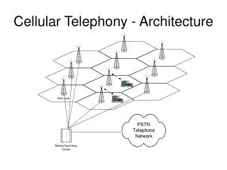
GMSC GMSC NLD HLR HLR VMSC/VLR UK Subscriber Inbound Roamer registration - Location Update-Diagram WB BSNL UK 1. UpLoc 1. UpLoc 2.ISD 2.ISD 3. ISD_resp 3. ISD_resp 4.UPL_resp 4.UPL_resp SCCP CdPA: 44-181-HLRUK CgPA: 919434099995 (VLR1) 2.ISD SCCP CdPA: 919434099995(VLR) CgPA: 44-181-HLRofUK1 MAP IMSI: 234-15-123456 MSISDN: 44-181-654321 1. UpLoc SCCP CdPA: 44-181-123456 (MGT derived from IMSIS analysis) CgPA:919434099995(VLR) MAP IMSI: 234-15-123456 MSC/VLR:919434099995
Call from an MS(MO Calls) • The MS uses RACH to ask for a signaling channel. • The BSC/TRC allocates a signaling channel,using AGCH. • The MS sends a call set-up request via SDCCH to the MSC/VLR.Over SDCCH all signaling preceding a call takes place (e.g.,authentication, ciphering,sending B-subscriber’s number,checking of o/g barring parameter etc.).
MO CALL Continued.. • The MSC/VLR instructs the BSC/TRC to allocate an idle TCH.The RBS and MS are told to tune to the TCH. • The MSC/VLR forwards the B-number to an exchange in the PSTN,which establishes a connection to the subscriber. • If the B-subscriber answers,the connection is established.
Call to an MS (MT Calls) • The PSTN subscriber dials in the MS’s telephone number (MSISDN).The MSISDN is analyzed in the PSTN,which identifies that this is a call to a mobile network subscriber.A connection is established to the MS’s home GMSC. • The GMSC analyzes the MSISDN to find out which HLR the MS is registered in,and queries the HLR for information about how to route the call to the serving MSC/VLR. • The HLR translates MSISDN into IMSI,and determines which MSC/VLR is currently serving the MS.
MT Calls continued.. • The HLR requests an MSRN from the serving MSC/VLR.The MSC/VLR returns an MSRN via HLR to the GMSC. • The GMSC analyses the MSRN and routes the call to the MSC/VLR. • The MSC/VLR knows which LA the MS is located in.A paging message is sent to the BSC’s controlling the LA. • The BSC’s distribute the paging message to the RBS’s in the desired LA.
MT Calls continued.. • The RBS’s transmit the message over the air interface using PCH with IMSI/TMSI. • When the MS detects the paging message,it sends a requests on RACH for a SDCCH. • The BSC provides a SDCCH,using AGCH. • SDCCH is used for the call set-up procedures.Over the SDCCH all signaling preceding takes place. • The MSC/VLR instructs the BSC/TRC to allocate an idle TCH.The RBS and MS are told to tune to the TCH.The mobile phone rings.If subscriber answers,the connection is established.
GMSC GMSC NLD HLR HLR VMSC/VLR UK Subscriber Call to an MS(MT Calls) in Roaming-Diagram UK PSTN IAM WB BSNL 5.ISUP IAM 5.ISUP IAM 6.ACM DIALS 2.PRN 2.PRN 7.ANM 8.REL 3.PRN ACK 3.PRN ACK 6.ACM 2.PRN 1.SRI 3.PRN ACK IMSI 9.REL ACK 3.PRN ACK 2.PRN 7.ANM MSISDN MSRN 5.ISUP IAM MSRN 9.REL ACK 4.SRI ACK 6.ACM 8.REL MSRN 7.ANM 9.REL ACK 6.PAGING 8.Disconnect 44-181-123456
GMSC GMSC NLD HLR HLR VMSC/VLR UK Subscriber MO SMS -Diagram UK WB BSNL MO -FSM MO -FSM MO-FSM-RSP MO-FSM-RSP MO -FSM MO-FSM-RSP SMSC SCCP CdPA: 919434099995(VLR) CgPA: 44-181-HLRofUK1 • An MS establishes a connection to the network, as in the normal call set-up. • The MS sends the short message using SDCCH to the SMSC via MSC/VLR.The SMSC in turn forwards the short message to its destination. SCCP CdPA: 44-181-123456 (MGT derived from IMSIS analysis) CgPA:919434099995(VLR) MAP IMSI: 234-15-123456
MT SMS • A user sends a message to a SMSC. • The SMSC sends the message to the SMS-GMSC. • The SMS-GMSC queries the HLR for routing information. • The HLR returns routing information to the SMS-GMSC. • The SMS-GMSC reroutes the message to the MSC/VLR. • The MS is paged and a connection is set up between the MS and the network,as in the normal call set-up case.
MT SMS Continued… • The MSC/VLR delivers the message to the MS.Short messages are transmitted on SDCCH. • If the delivery was successful,a report is sent from the MSC/VLR to the SMSC,if not,the HLR is informed by the MSC/VLR, and a failure report is sent to SMSC. • The HLR then informs the SMSC when the MS becomes available.
GMSC GMSC NLD HLR HLR VMSC/VLR UK Subscriber MT SMS -Diagram UK WB BSNL-Circle1 SRI-SM ACK 5. MT-FSM_resp 5. MT-FSM_resp 1. MT-FSM 1.MT- FSM SRI-SM 1. MT-FSM 5. MT-FSM_resp 1. MT-FSM SMSC SMS CdPA:44-181-123456 SCCP CdPA: 91-9434099995 MSC/VLR CgPA: 44-181-SMSCofUK1 SCCP CdPA: 44-181-SMSCofUK1 CgPA:919434099995(MSC/VLR)
PREPAID SYSTEM • Prepaid system adds few other nodes than the existing GSM network. • It is the IN system which handles the prepaid subscriber. • IN system consist of Mainly 1.SCF 2.SDP 3.PPAS 4.IVR • In MSC SSF module handles the prepaid call Scenario in MSC side.
GPRS • GPRS Core network consists of • SGSN:Serving GPRS Support Node; the gateway between the RNC and the core network in a GPRS/UMTS network • GGSN:Gateway GPRS Support Node; the gateway between a cellular network and a IP network.
GPRS RELATED LINKS • Gc-The interface between the GGSN and the HLR in a GSM/GPRS network • Gd-The interface between the SGSN and the SMSC in a GSM/GPRS network • Gf-The interface between the SGSN and the EIR in a GSM/GPRS network • Gi-The interface between the GGSN and the Internet in a GPRS network • Gn-The interface between the GGSN and the SGSN in a GPRS network • Gp-The interfaces between the GGSN/SGSN and the Border Gateway in a GPRS network • Gr-The interface between the SGSN and the HLR in a GPRS network • Gs-The interface between the SGSN and the MSC in a GSM/GPRS network
GPRS ATTACH 8.ISD ACK HLR SGSN 7.ISD 6.update location 5.Equipment idemtity check response 1.GPRS ATTACH REQUEST EIR 2.Authentication request 4.Equipment identity check 3.Athentication res 9.GPRS attach accepted
PDP Context activation 5.Radius authentication request 2.DNS query (APN) 1.Activate PDP contest SGSN DNS SERVER GGSN Radius Server DHCP SERVER 6.Res 7.DHCP ADDR.REQ 3.DNS Resp(GGSN IP ADR 8.DHCP ADDR.RES 10. Activate PDP Context Accept 4.Create PDP Contest req. 9. Create PDP Context Response
CDMA (IS-95) TECHNOLOGY • Code-Division Multiple Access, a digital cellular technology that uses spread-spectrum techniques • IS-95 CDMA system operates in 800 Mhz • CdmaOne is the brand name of IS-95 technology from 1997. • CdmaOne is basically an air-interface standard. • IS-95 uses Frequency division duplex.Forward link and reverse link transmission occur in different frequency band.
Duplex separation used in IS-95 is 45Mhz • Carrier spacing is 1.25 Mhz • Forward link frequency: 824-849Mhz • Reverse Link frequency: 869Mhz-894Mhz • The forward link consists of Base station(BS) transmitter,radio channel and the MS receiver.
CDMA Continues… • CdmaOne system supports four different types of forward channels #Pilot channel-is continuously transmitted by each CDMA carrier and is used by MS to identify the BS and to asses the suitability of the cell hand over.In this respect it may be likened to the BCCH carrier in GSM system. #Synchronous channel-Itallows MS to achieve time synchronization with BS and the network. #Paging channel-is used to page MSs to alert them to an incoming call. #Traffic channel-are assigned to the users as required and they may carry speech or user data at bit rates of up to 9.6 kbps. Ø
Each forward channel on a CDMA carrier is assigned a different 64-bit Walsh code. • The reverse link radio path consists of the Mobile station(MS) transmitter,the radio channel and the base station(BS). • CdmaOne system supports two different types of radio channel on reverse link #Access channel-as its name would suggest,is used by MS initially to access the network,e.g. at call initiation or in response to a paging message.Each Base Station may support 32 access channels per forward link paging channel and the MSs within a CeLL are pseudo-randomly distributed between the access channels.
CDMA Continues… Access channel data are presented in the form of one 96-bit frame every 20 ms.Of this 96 bits,88 are used to carry information and remaing eight are encoder tail bits. #Traffic channel-are assigned to the individual user as required.A reverse link traffic channel may carry speech and data at bit rates up to 9.6 kbps.
The cdmaOne MS does not transmit a pilot signal as this would significantly decrease reverse link capacity. • BS receiver uses RAKE receiver to demodulate the reverse link signal from a particular MS. • MS handover process occur by measuring the strength of the pilot channels signal from a BS other than its current BS. • CdmaOne system supports three main types of handover
CDMA Continues… #Idle mode handover-It occurs when an MS moves from the coverage area of one BS into the coverage area of a second BS while an MS is an idle mode. # Soft handover- is used between BSs having CDMA carriers with identical frequency assignments. # Hard handover- occur when a mobile is switched between two BSs using different carriers.
Simplified data flow for the access procedure of a mobile terminated call.
CDMA 2000 • This is the evaluated 3G version of IS-95/cdmaOne technology. • CDMA2000 is an ITU-approved standard that was the first 3G technologies (October,2000). • provides advanced voice communications and high-speed data connectivity, including access to the Internet, mobile data applications and multimedia content. • Supports data services at minimum transmission rates of 144 kbps in mobile (outdoor) and 2 Mbps in fixed (indoor) environments. • The world's first 3G commercial system was launched by SK Telecom (South Korea) in October 2000 using CDMA2000
CDMA2000 represents a family of standards and includes >CDMA2000 1X >CDMA2000 1xEV-DO Technologies >CDMA2000 1xEV-DO Rev A >CDMA2000 1xEV-DO Rev B >Ultra Mobile Broadband - UMB (CDMA2000 1xEV-DO Rev C)
CDMA 2000 continues… • CDMA2000 builds on the inherent advantages of CDMA technologies,such as >introduction of Orthogonal Frequency Division Multiplexing (OFDM and OFDMA) >advanced control and signaling mechanisms >improved interference management techniques end-to-end Quality of Service (QoS)